Bradford White M-I-MH40T6FLX User Manual
Page 15
15
Gas Conversion Instructions continued-
ii) Remove (2) 1/4” hex drive screws from right side inner door.
iii) Remove (2) 1/4” drive screws from flange section of inner door.
iv) Remove (2) 1/4” drive screws from left side inner door.
v) Remove inner door and inspect per step 4b.
b) Fully inspect inner door gaskets for the following:
Tears
Missing
Material
Cracks
Dirt or debris
Other imperfections that will inhibit proper seal
Gasket adhesion to inner door
Material left on combustion chamber (around opening)
c) If the gasket is not affected by any of the above, gasket replacement is not
required.
d) If gasket replacement is required, contact manufacturer for inner door gasket
replacement kit.
5) Disconnect thermocouple, gas supply tube and pilot tube from the gas valve and
remove the burner assembly from the water heater.
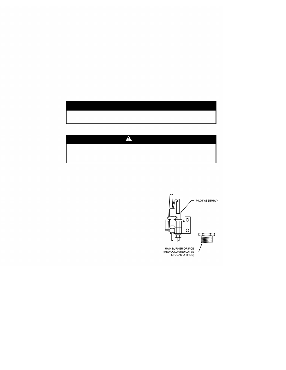
6) Remove the “RED” color coded L.P. orifice and pilot assembly and replace with
natural gas orifice and pilot assembly provided in the cloth bag attached to the
water heater.
7) Replace the burner assembly, reconnect all
fittings and check for leaks. Refer to “Gas
Connections”.
8) Replace inner doors with the following
procedure.
a) Clean any residual gasket residue or other
debris from combustion chamber surface
before installing the inner door/gasket
assembly.
IMPORTANT
If gasket replacement is required, contact manufacturer for inner
door gasket replacement kit.
WARNING
If the information in these instructions is not followed exactly, a
fire or explosion may result causing property damage, personal
injury or death.