Bradford White M-1-TW-60T6FSX User Manual
Page 17
TTW1 Universal Service
Replacement Blower
MITW -12 / -15 Series
Page 17
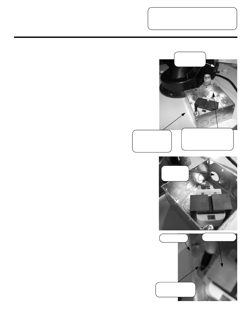
Step 12.
a.) Position the junction box, P/N
239-47196-00, on top of the water
heater, in front of the blower, and on
the side nearest the T&P valve.
b.) Place the transformer, P/N
265-44072-01, inside the junction box
such that there is sufficient room
between its (4) posts and the sidewalls
of the junction box. Determine the side
to remove a knock-out. Remove the
transformer from the junction box.
c.) On a side opposite the transformer's
posts, remove (1) knock-out ¾" in size.
Then, place the junction box back on
the water heater and the transformer
back into the box.
d.) Mark the location of the mounting
holes of the transformer onto the
junction box.
e.) Remove the transformer from the
junction box.
f.) Drill (2) 1/8” diameter holes in the
locations that were marked in Step
12d. Be sure that the pilot holes are
through the junction box and jacket
head.
Place junction box
on top of water
heater and
transformer in box.
Leave room in corner
closest to blower harness
receptacles to attach
terminals to transformer.
Blower
harness
receptacles
Remove ¾"
knockout.
Mark the location of
transformer in box.
Junction box
Transformer