Bradford White M-1-TW-60T6FSX User Manual
Page 15
TTW1 Universal Service
Replacement Blower
MITW -12 / -15 Series
Page 15
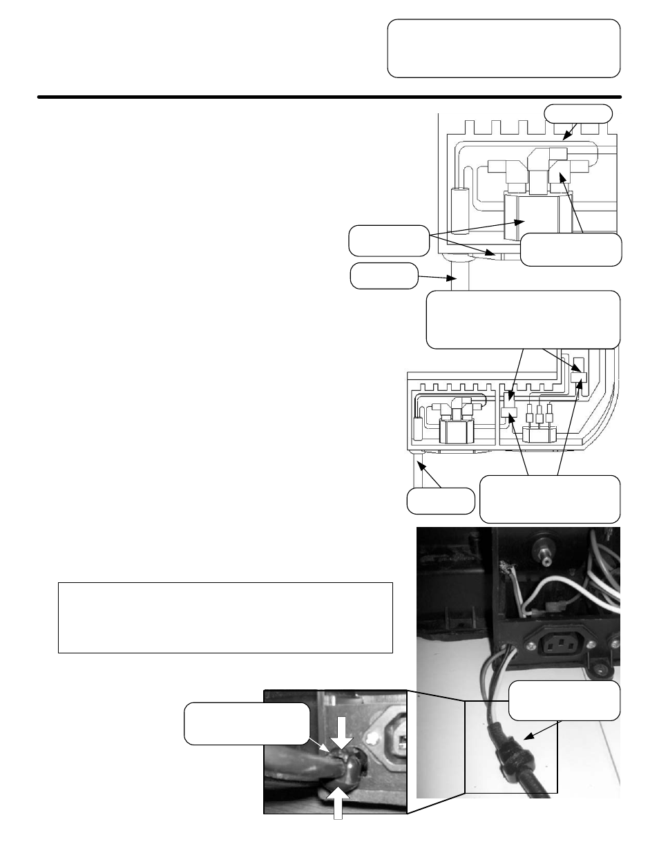
Step 9.
b.) Inside the access compartment, follow
the black wire from the power cord until
you reach the flag terminal attached to
the end of the wire. Disconnect black
wire from the back of the power inlet
connector.
c.) Just below the crimp connector, cut
the (3) white (neutral) wires. Remove
the white power cord lead from the
bundle. Then, strip the ends of the (2)
remaining white wires and connect
them using a wire nut, included with
the kit, P/N 239-47281-00, and tuck the
wires back into the lower portion of the
access compartment.
d.) Just below the crimp connector, cut the
(3) green (ground) wires. Remove the
green power cord lead from the
bundle. Then, strip the ends of the (2)
remaining green wires and connect
them using a wire nut, included with
the kit, P/N 239-47281-00, and tuck the
wires back into the lower portion of the
access compartment.
e.) Remove the power cord from the
blower housing and discard.
Squeeze bushing to
remove power cord
from blower.
Remove black
wire’s flag terminal
Power cord
Black wire
Power inlet
connector
Warning:
Make sure that each wire nut is securely
tightened and that all wires are making
good connection or improper water heater
operation will occur.
Push in both sides of
the bushing with pliers
to remove.
Connect (2) white wires
and (2) green wires, each
with their own wire nut.
Power cord
Cut just below these crimp connectors.
Then, remove (1) white and (1) green
wire from bundles. Trace wires back
to power cord.