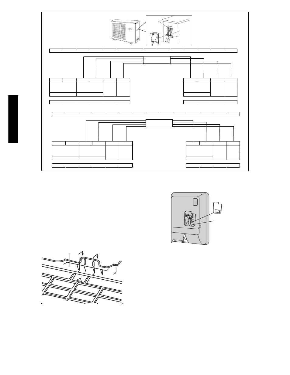
38/ 40gx c (q ), Fig. 12 --- field wiring – Carrier 40GXQ User Manual
Page 8
8
G
Terminal Block
Conduit panel
Conduit
Outdoor
unit
L
N
L
N
GND
S
L
N
GND
S
Ground
Control
Indoor Unit
Pow er
Ground
Control
Indoor
Pow er
38GXQ-40GXQ009, 012 115-1-60 Connection Diagram
All 40GXQ 115-1-60 Indoor Units
Supply
Unit
Supply
115-1-60
115-1-60
115-1-60
All 38GXQ 115-1-60 Outdoor Units
CONNECTING CABLE
OUTDOOR TO INDOOR
Main
Pow er to
L1
L2
L1
L2
GND
S
L1
L2
GND
S
Ground
Control
Ground
Control
All 38GXQ 208/230-1-60 Outdoor Units
All 40GXQ 208/230-1-60 Indoor Units
Supply
Unit
Supply
208/230-1-60
208/230-1-60
208/230-1-60
Pow er
Indoor
Pow er
38GXQ-40GXQ012, 018 & 024 208/230-1-60 Connection Diagram
CONNECTING CABLE
OUTDOOR TO INDOOR
Main
Pow er to
Indoor Unit
A09666
Fig. 12
--- Field Wiring
INSTALL ALL POWER, INTERCONNECTING
WIRING, AND PIPING TO INDOOR UNIT.
1. Run interconnecting piping and wiring from outdoor unit to
indoor unit.
2. Pass interconnecting cable through hole in wall (outside to
inside).
3. Lift indoor unit into position and route piping and drain
through hole in wall (inside to outside). Fit interconnecting
wiring into back side of indoor unit.
4. Hang indoor unit on upper hooks of wall mounting plate (as
shown in Fig. 13)
A08283
Fig. 13
--- Hanging Indoor Unit
5. Open front cover of indoor unit and remove field wiring ter-
minal block cover (see Fig. 14)
Field Wiring
Cover
Interconnecting
Cable
A08279
Fig. 14
--- Field Wiring Cover
6. Pull interconnecting wire up from back of indoor unit and
position in close to the terminal block on indoor unit.
7. Push bottom of indoor unit onto mounting plate to com-
plete wall mount.
8. Connect wiring from outdoor unit per connection diagram
(see Fig. 12).
NOTE:
Polarity of power wires must match original
connection on outdoor unit.
9. Replace field wiring cover and close front cover of indoor
unit.
10. Connect refrigerant piping and drain line outside of indoor
unit. Refer to Fig. 10 for proper installation of flare connec-
tions. Complete pipe insulation at flare connection then
fasten piping and wiring to the wall as required. Com-
pletely seal the hole in the wall.
38/
40GX
C
(Q
)