Workrite Cascade Assembly Instructions for 2-Leg Counterbalance Workcenters User Manual
Page 5
Magnetic
24" top 2.8"
30" top 5.8"
Center
ed Left to right
Workrite Ergonomics | 800.959.9675 www.workriteergo.com
5 of 8
Workrite Cascade Workcenter - Assembly Instructions
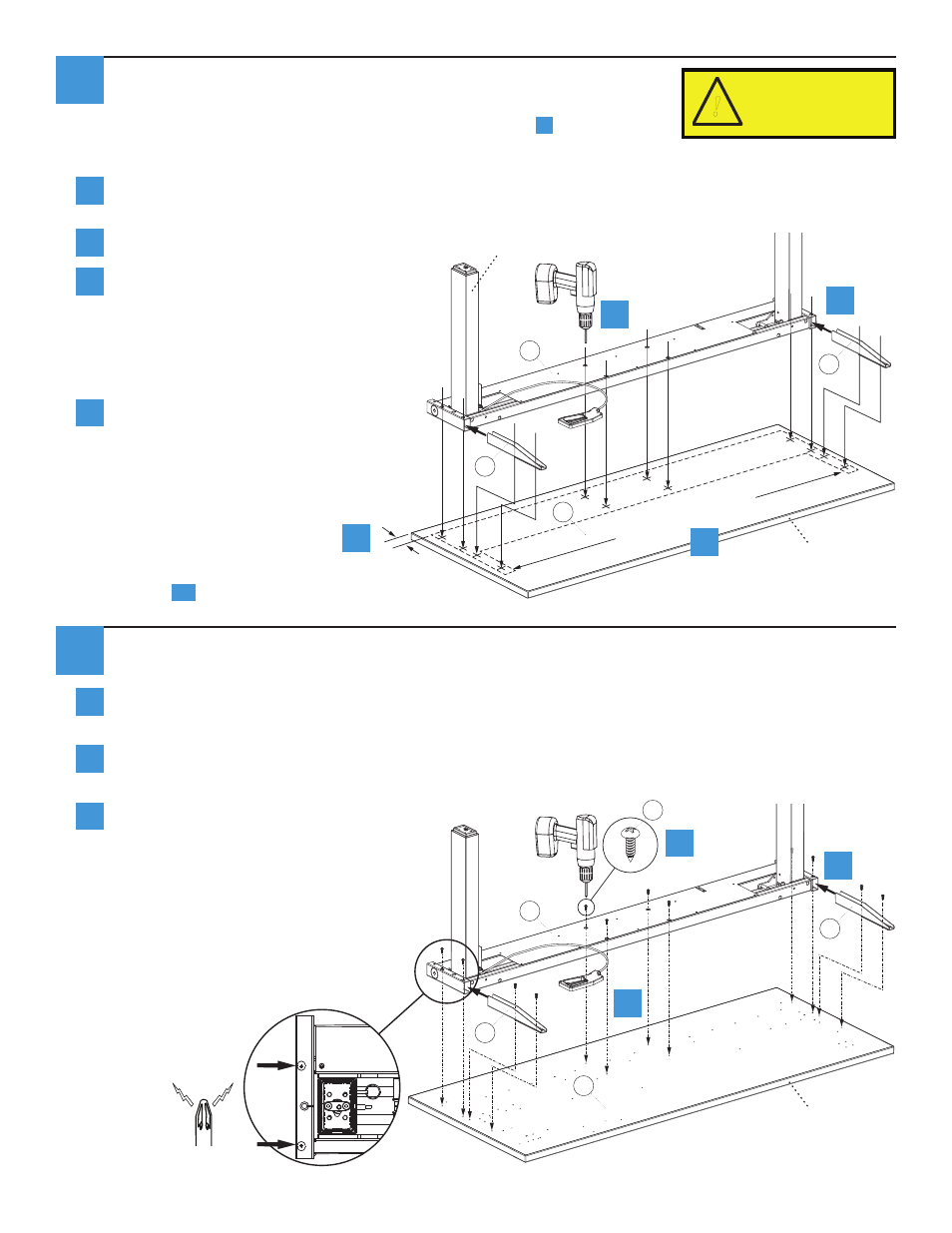
Attach Base to Worksurface
If you have a Workrite worksurface:
Position the Base Assembly (B) to align mounting holes in brackets to holes in the Worksurface (A).
Insert the Cascade Bracket (D) into the frame tubes at both ends of the Base Assembly and align
the holes for the Brackets with the holes in the frame tubes.
Attach Base Assembly and Brackets
to the Worksurface (A) using Pan
Head Top Screws (G). You will need
to use a #3 Phillips head magnetic-
bit driver. Screws will pass through
the large holes in the Base Assembly
and attach to the underside. If you
use an electric screwdriver, be sure
it is on the lowest torque setting to
avoid stripping the holes in the top.
A magnetic-bit
driver is essential
for these screw
locations.
Center Base on Worksurface
If you have a Workrite worksurface skip to step
6
If you do not have a Workrite worksurface:
Align the Base Assembly (B) from the back on the bottom side of your worksurface (A). 24”
worksurfaces are 2.8” from back, 30” worksurfaces are 5.8” from back.
Center the Base Assembly left to right.
Insert the Cascade Brackets (D) into
the frame tubes of the Base Assembly
and align the holes of the Brackets
with the holes in the frame tubes.
Carefully mark all 12 mounting holes,
then remove the base from the
worksurface.
Use ⅛" drill bit to drill pilot holes at
marked locations. Mark your drill
bit so you do not drill any more
than ¾" deep and damage your
worksurface top!
Realign the base assembly
with the pilot holes then go
to step
6c
.
a
Mark your drill bit at
3/4” or use a drill
stop or you may
damage your top!
!
D
D
D
D
A
G
5
6
a
a
b
c
d
c
b
c
b
c
a
b
Right Leg
A
B
d
B
front
front