Ba a – Workrite Cascade Assembly Instructions for 2-Leg Counterbalance Workcenters User Manual
Page 4
4 of 8
Workrite Ergonomics | 800.959.9675 www.workriteergo.com
Workrite Cascade Workcenter - Assembly Instructions
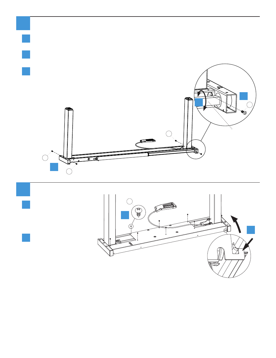
Lock Legs into their vertical position
Use the 5 mm Allen Wrench to attach four #M8 × 14 mm Socket Head Cap Screw (F) to the outer
leg mounts at the base of both legs.
Note: You may need to rotate the Counterbalance Adjustment Rod to be flat so you can more
easily access the hole behind, to insert and tighten the screw.
Use the 5 mm Allen Wrench to tighten the four pre-installed
Socket Head Cap Screws at the inner leg mounts on both legs.
Replace Cover Plate
Lift the Base Assembly to
align the cover tabs to the
notches in the top of the
frame and place cover onto
base.
Replace the eight M4×10
screws (E) to secure the
Cover Plate.
b
b
a
a
lift
F
F
F
F
E
3
4
a
b
b
c
a
a
Counterbalance
Adjustment Rod
Teri Says these were
tightened by supplier