Connect cables to the cpu – Welch Allyn Acuity LT 7.0X Install Guide Addendum - Installation Guide User Manual
Page 2
2
80015174 A
Welch Allyn Acuity LT Central Monitoring System
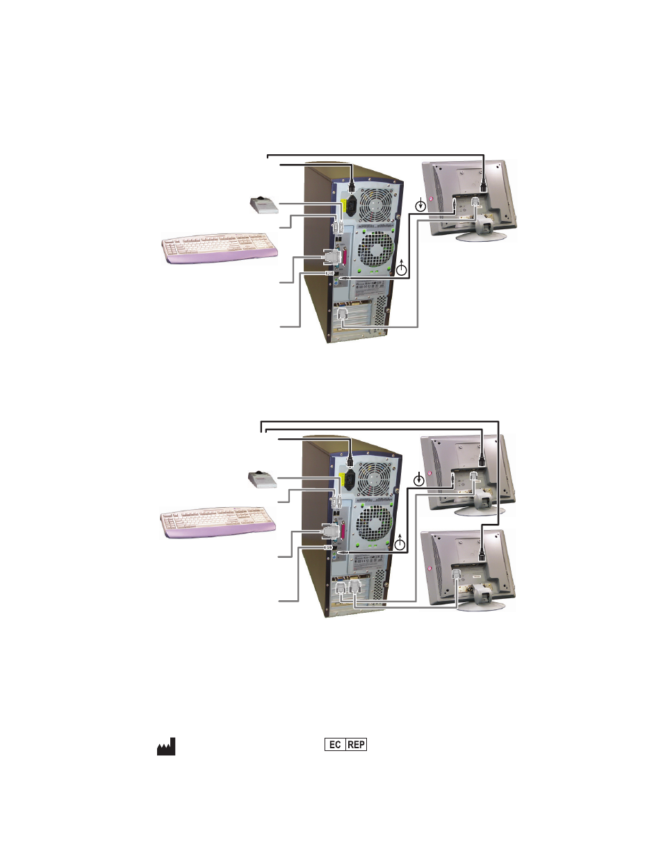
Connect cables to the CPU
Please refer to the appropriate diagram when you connect cables to the Acuity LT CPU.
12-patient Acuity LT system:
28-patient Acuity LT system:
UPS 2
Do not plug UPS 2 into AC
power until final system check.
Printer
Do not plug the printer into a UPS.
Plug it directly into an AC outlet.
Display
Use analog HD-15
monitor connector
for patients 1-12.
Trackball
Keyboard
To terminal server (Hardwired
Acuity LT System) or to switch
(Wireless Acuity LT System)
CPU
© 2009 Welch Allyn Protocol, Inc. All rights are reserved. No one is permitted to reproduce or duplicate, in any
form, this document or any part thereof without written permission from Welch Allyn.
REF 102608
Addendum 80015174A, 2009-02
.welchallyn.com
Welch Allyn Protocol, Inc.
8500 SW Creekside Place
Beaverton, OR 97008-7101 USA
Welch Allyn Ltd
Navan Business Park
Dublin Road, Navan
County Meath, Republic of Ireland
UPS 2
Do not plug UPS 2 into AC
power until final system check.
Trackball
Keyboard
Printer
Do not plug the printer into a UPS.
Plug it directly into an AC outlet.
To terminal server (Hardwired
Acuity LT System) or to switch
(Wireless Acuity LT System)
Display 2
Use digital DVI
monitor connector
for patients 13-28.
Display 1
Use analog HD-15
monitor connector
for patients 1-12.
CPU