Overlay door panel installation, Step 5: assemble lock parts, Step 6: install lock cam – Vintage Cellars MP24WD User Manual
Page 16: Step 4: assemble the panel to the door
16
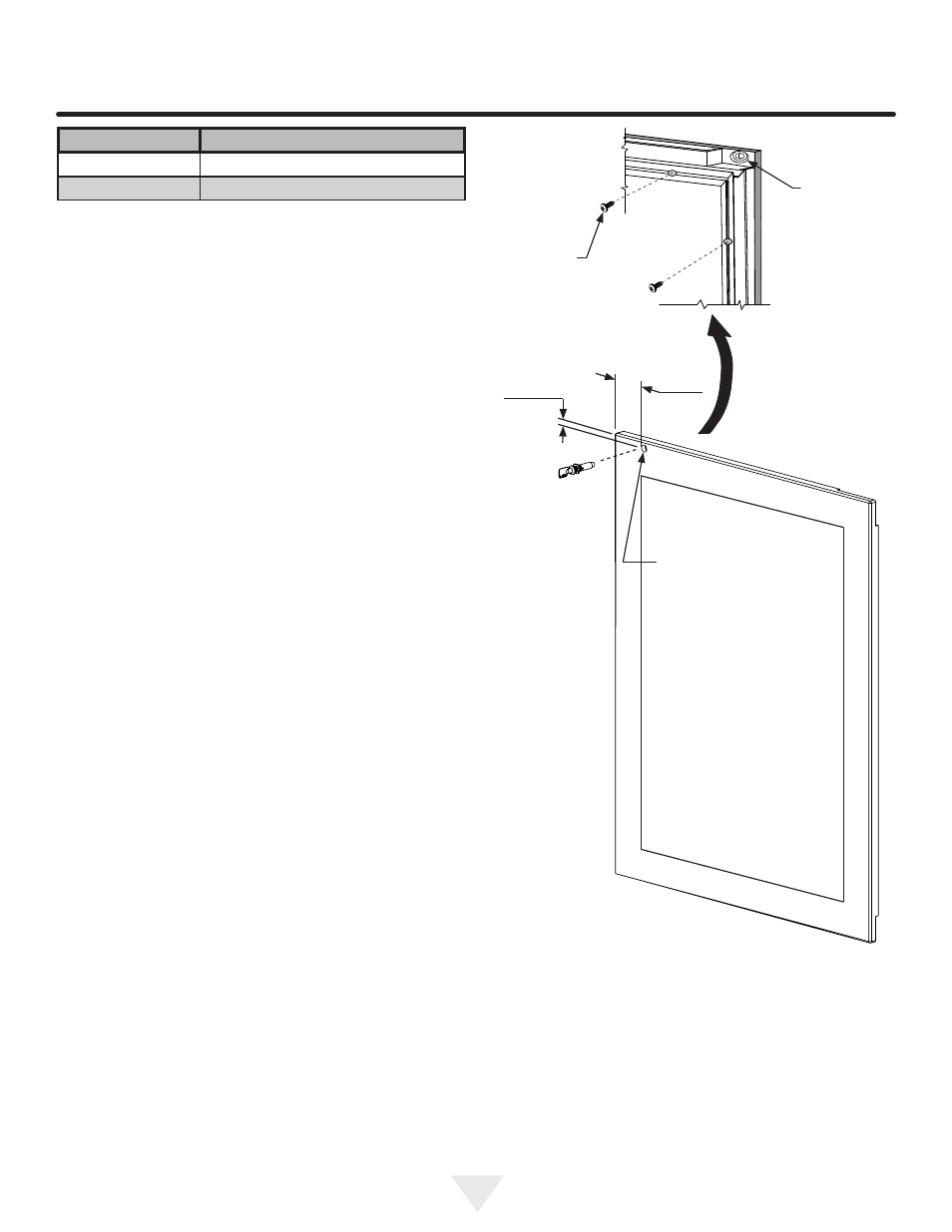
Counter bore
lock hole
on back side.
Figure 19a
#10 x
1
⁄
2
"
screw
Figure 19
Hinge side of door
1
⁄
2
" (13 mm) diameter
drill through door panel,
from other side (see
detail above)
13
⁄
16
"
(20.5 mm) counter bore,
7
⁄
16
" (11 mm) deep.
17
⁄
32
"
(13.7 mm)
3
1
⁄
2
"
(89 mm)
OVERLAY DOOR PANEL INSTALLATION
Step 5: Assemble lock parts
Two (2) lock extensions are provided with the lock. Use the
longer extension for
3
⁄
4
" thick overlay panels and the shorter
one for
5
⁄
8
" thick overlay panels. Assemble the lock exten-
sion, cam stop washer, spring washer, and set screw to the
lock as shown in Figure 20 and 21.
Install this lock assembly into the lock hole in the overlay
panel and secure with the retaining nut on the back side
with a 15 mm socket and ratchet. Make sure the key slot in
the front of the lock is vertical.
Step 6: Install lock cam
Attach the lock cam to the back of the lock assembly with
the phillips head screw provided. Orient the lock cam verti-
cally when installing on the lock.
Step 4: Assemble the panel to the door
The preferred method of attaching the panel to the door
is to clamp the panel to the door so it cannot move while
drilling the screw pilot holes. Use bar clamps or "C" clamps
with pads on the clamping surfaces that will not mar the
panel or the door. The custom overlay panel should be
flush with the top of the door and centered along the width
of the door. See Figure 10a. Drill holes through the gasket
extrusion using the 10 holes as pilot holes. Use the drill
size from the chart in Table "C", being careful not to drill
through the front surface of the panel, drill no deeper than
1
⁄
2
" (12.7 mm) deep. If the overlay panel is thinner than
5
⁄
8
" (16 mm) thick shorter screws will have to be obtained.
Fasten the panel to the door with the 10 screws provided in
the literature pack. (See Figure 19a). Remove the clamps
and replace the gasket in the gasket extrusion channels of
the door. Some force may be required to seat the gasket
into the channels. Be sure the gasket corners are seated
properly.
Material Type
#10 Wood Screw
Hardwood
1
⁄
8
" (3.2 mm) Diameter. Pilot Hole
Softwood
7
⁄
64
(2.8 mm) Diameter. Pilot Hole
Table C