Vetter Struts and Accessories User Manual
Page 21
Page 21/24
Wall Strut Assembly:
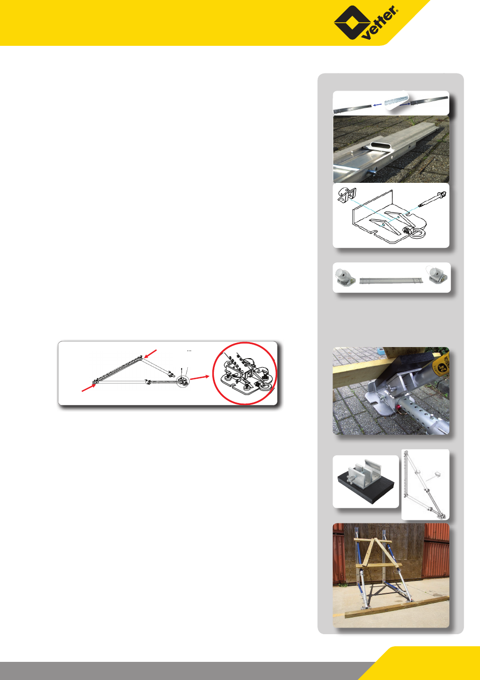
1. Connect 2 rail elements ART-RR5, 1.5 m with the rail adapter
ART-RRA. Slide the adapter into a rail profile, secure and lock
it with the safety pin. The second rail element is also placed as
described and secured and locked with the safety pin.
2. The angle joint ART-C45 is placed with its functional side onto
the base plate ART-BPB12 and is secured and locked with the
safety pin.
3. One angle joint ART-P45 and ART-P60 each are slid with their
base plates into the rail ends, fixed and secured with the safety
pins. The angle joint ART-P60 should be fixed at the upper part
of the rail if the rails are assembled with the ART struts.
4. Set the ART-F7-11 strut onto the mounting head of the ART-P60
joint with the support tube and secure the strut by locking it.
Connect the piston of the ART-F/-11 strut with the ART-C45
joint of the base plate ART-BPB12 and set the ART-RRA rail ad-
apter in last possible position of the ART-F7-11 strut piston.
Secure and lock with the safety pin. The ARTE4.5-7 strut is set
with the strut onto the mounting head of the ART-P45 joint
and is locked.
Gelenk ART-P60
Gelenk ART-P45
ART-P45 Joint
ART-P60 Joint
Set the ART-E24 extension onto the ARTE4.5- 7 strut piston
and connect this with the mounting head of the ART-RRA ad-
apter.
Check whether all locks are engaged and that all com-
ponent safety pins are in position and locked! The ART
struts must be secured as described!
5. Four nail plates with exchangeable nail surfaces are part of the
set composition for securing in diagonal or transverse posi-
tions with appropriately stable and strong wood material. The
nail plates can be fixed to the support tube and onto the pis-
ton with a clamp screw connection.
Securing the wall struts must be carried out as described or as
shown on the photographs. However, the type and method of
securing very much depends on local conditions.