Tycon Power TPDIN-Monitor-WEB User Manual
Page 2
2
STEP 4:
Connect any power to devices you want to be under relay con-
trol to the CHI—CH4 relays. The relays are normally closed relays so
activating the relay will open the relay.
STEP 5:
Connect the External Temperature sensor to the included
green wire terminal connector. Connect the wires to IN– and IN+ termi-
nals. Plug the wire terminal connector to the “Temp.” connector loca-
tion. Locate the external temperature sensor where you want to meas-
ure external temperatures. You can extend the wire lengths if desired
by soldering additional wires to the existing wires. You can measure
temperatures from –40C to +125C
STEP 6:
The TPDIN-Monitor-WEB can be powered with 10-58VDC thru
wire terminal connector #7 or via 802.3af or Passive 48V POE thru the
RJ45 POE/DATA port.
STEP 7:
Download the Discovery Tool from
he TPDIN-Monitor-WEB
ships with IP addressing by DHCP enabled. The discovery tool will find
the IP address of the device so you can access the web control panel. If
not connected to a DHCP server the default IP address is 192.168.1.2
STEP 8:
Open the Web control panel of the unit by using the discovery
tool or typing the units known IP address into a browser. The unit will
serve up the Monitor web page. The monitor page is where all the volt-
age, current, temperature and relay status can be seen. Relays can
also be controlled manually from this page. There is a cycle button by
the relays if you want to automatically cycle a relay from on to off and
back. The cycle delay is specified on the SYSTEM page.
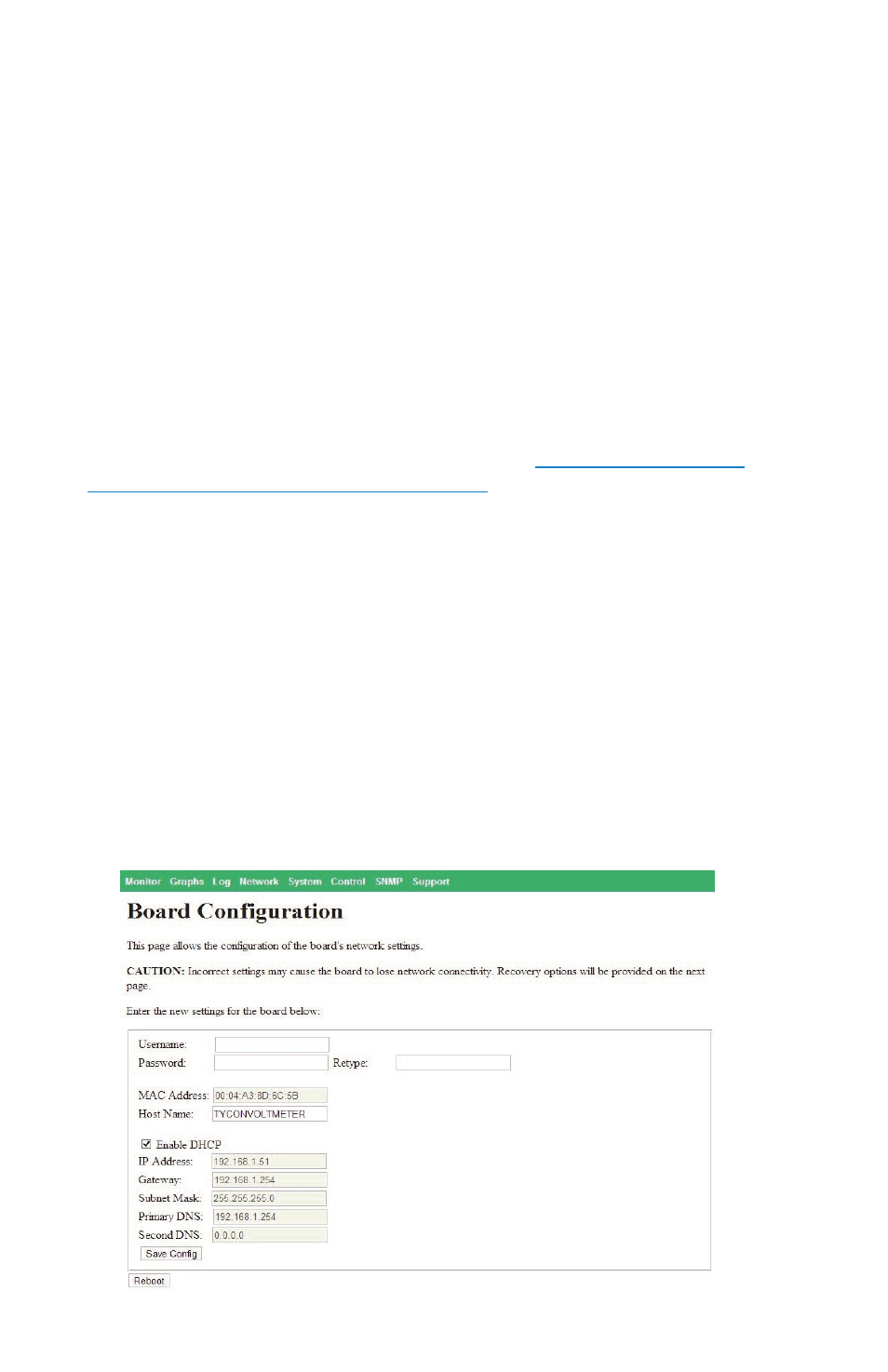
STEP 9:
Open the Network Page. Here you can set a static IP Address.
You can also set access security by entering a user name and pass-
word (10 characters max). You can also set a unique Host Name to
identify the Monitor.