Tjernlund XCOP1 Constant Operating Pressure Exhaust Control 8504175 (Discontinued) User Manual
Page 6
5
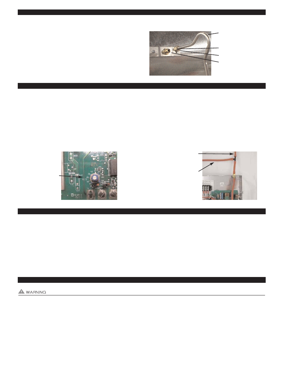
PRESSURE SENSING TUBE INSTALLATION
1. Follow sensing tube location recommendations on page 4.
Use a sharp drill bit to reduce burr, drill a 1/4" hole for pressure
sensing tube. Screw sensing tube bracket to duct/chase with
sampling hole centered, (See Diagram C).
2. Insert stainless steel sensing tube through 1/4" hole enough to
just penetrate interior of duct/chase and lock in place with com-
pression ferrule and nut, (See Diagram C).
ADJUSTING THE PRESSURE (EXHAUST) SET POINT
1. Verify that slot on set point adjustment pot for the COP controller is aligned with the "20" hash mark, (See Diagram D).
2. Provide power to the XCOP1 by turning on circuit breaker or disconnect or activating dryers if using a dryer duct pressure switch.
3. Verify that the RT-Series Fan activates by seeing the draft pressure increase (more negative) on your draft gauge as measured
with a tee at draft sensing position, (See Diagram E). Gradually adjust the pot on the XCOP1 controller circuit board clockwise.
The RT-Series Fan should speed up increasing the negative exhaust pressure. Slowly adjust the pot on the XCOP1 controller
counter-clockwise until the exhaust pressure is maintained at -0.10" w.c.. NOTE: Turning the adjustment pot too far counter-
clockwise will cause the RT-Series Fan to stall or not be able to start. Readjust clockwise if necessary.
ADJUSTMENT OF BALANCING BAFFLE(S) FOR KITCHEN AND BATH FANS
IMPORTANT: Balancing Baffles must not be used for dryer applications due to the potential for lint buildup.
1. With all balancing baffles closed and starting with connection at lowest floor drill a small sampling hole in duct connection to the
chase 1 foot behind the Balancing Baffle (opposite side of chase connection).
2. With the XCOP1, RT-Series Fan and Bath/kitchen fans connected to the duct operating, gradually open the Balancing Baffle
until desired negative exhaust pressure is measured and lock in place. Typically a measurement of a -0.02 to -0.05" w.c. is
adequate.
3. Repeat steps 1 and 2 for each floor, moving up towards the RT-Series Fan.
TROUBLESHOOTING ELECTRICAL PROBLEMS
It is necessary to measure voltage during troubleshooting. Extreme caution must be exercised to prevent injury. If you are
unable to determine the defective part with the use of this guide, call your Tjernlund distributor or Tjernlund Products direct at
1-800-255-4208 for further assistance.
RT-SERIES FAN MOTOR DOES NOT OPERATE
Verify the XCOP1 control has power by checking for 115 VAC at the input power terminal strip positions L1 and N. If no voltage is
measured check circuit breaker, disconnect switch or any other switch between disconnect and XCOP1 control.
Voltage present: Verify wiring connections between XCOP1 and RT-Series Fan. Check adjustment pot on XCOP1. Too low of an
adjustment may stall RT-Series Fan. Adjust clockwise to see if RT-Series Fan speeds up. If RT-Series Fan does not speed up and
DIAGRAM C
1/4” STAINLESS STEEL
SENSING TUBE BEND MUST
FACE UPWARD
COMPRESSION FERRULE
COMPRESSION NUT
SAMPLING PORT CENTERED
OVER 1/4” HOLE
DIAGRAM E
TO PRESSURE SENSING
TUBE IN VENT COMMON
MANIFOLD
TO DRAFT GAUGE
DIAGRAM D
XCOP1 DRAFT
ADJUSTMENT POT
AND SCALE. CLOCK-
WISE WILL INCREASE
DRAFT.