Tjernlund XCOP1 Constant Operating Pressure Exhaust Control 8504175 (Discontinued) User Manual
Page 5
4
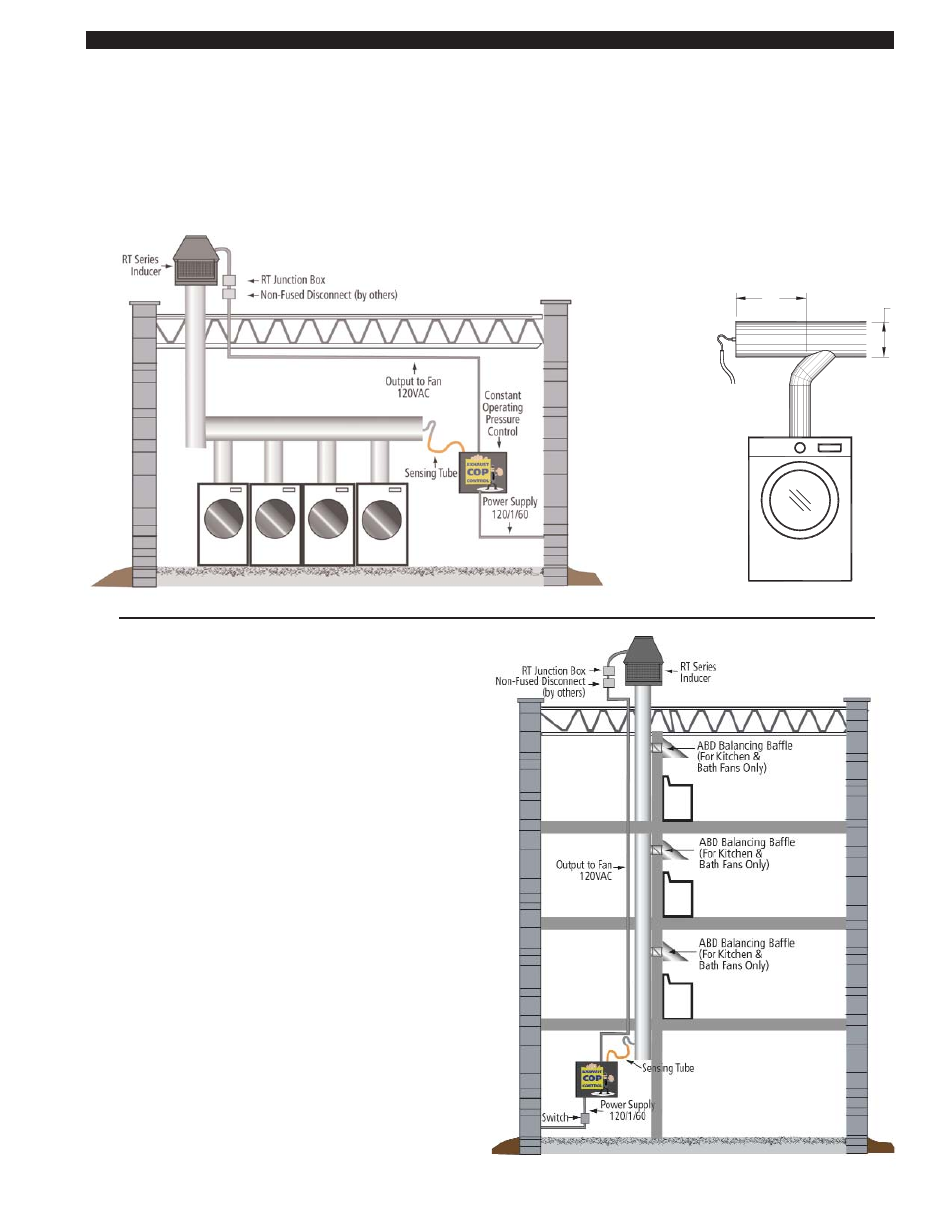
PRESSURE SENSING TUBE LOCATION
MULTIPLE DRYERS JOINED IN A COMMON HORIZONTAL DUCT
The sensing tube should be installed in the cap of a tee or at the rear of a common exhaust manifold, in back of the vent connector
that is farthest from the RT-Series Fan. The tee is necessary so that only static pressure is measured, (See Diagram A). If the
pressure sensing tube is installed in the side of a duct it will also measure velocity pressure, giving an incorrect signal back to the
XCOP1 Control. If mounting on the side of the duct is unavoidable, the sensing tube should be flush to the interior wall of the duct.
Avoid sampling near or in elbows. Duct connections should be sealed to prevent leakage or entrainment. Installer must provide
access for lint clean out.
MULTIPLE DRYERS, KITCHEN OR BATH FANS EXHAUSTED
INTO A COMMON VERTICAL CHASE
The sensing tube should be installed to sample the chase pres-
sure at a point below the lowest duct connection but above any
point in the clean out that may accumulate moisture or lint. If
sampling pressure in the side of a chase the sensing tube end
should be flush to the interior wall of the chase, (See Diagram B).
Duct connections should be sealed to prevent leakage or entrain-
ment of air. Installer must provide access for lint clean out.
BEHIND THE DRYER FURTHEST FROM INDUCER
BE LOCATED TWICE THE MANIFOLD DIAMETER
IF POSSIBLE, THE SENSING TUBE SHOULD
D
2D
DRYER FURTHEST
FIGURE 8054008 4/14/11
FROM THE INDUCER
MINIMUM
XCOP1
SENSING
TUBING TO
DIAGRAM A
DIAGRAM B
Chase Exhaust for Kitchens & Baths or Dryers
Multiple Clothes Dryers Common Vented
DRYER FURTHEST
FROM ROOFTOP FAN