Tjernlund XCOP1 Constant Operating Pressure Exhaust Control 8504175 (Discontinued) User Manual
Page 3
2
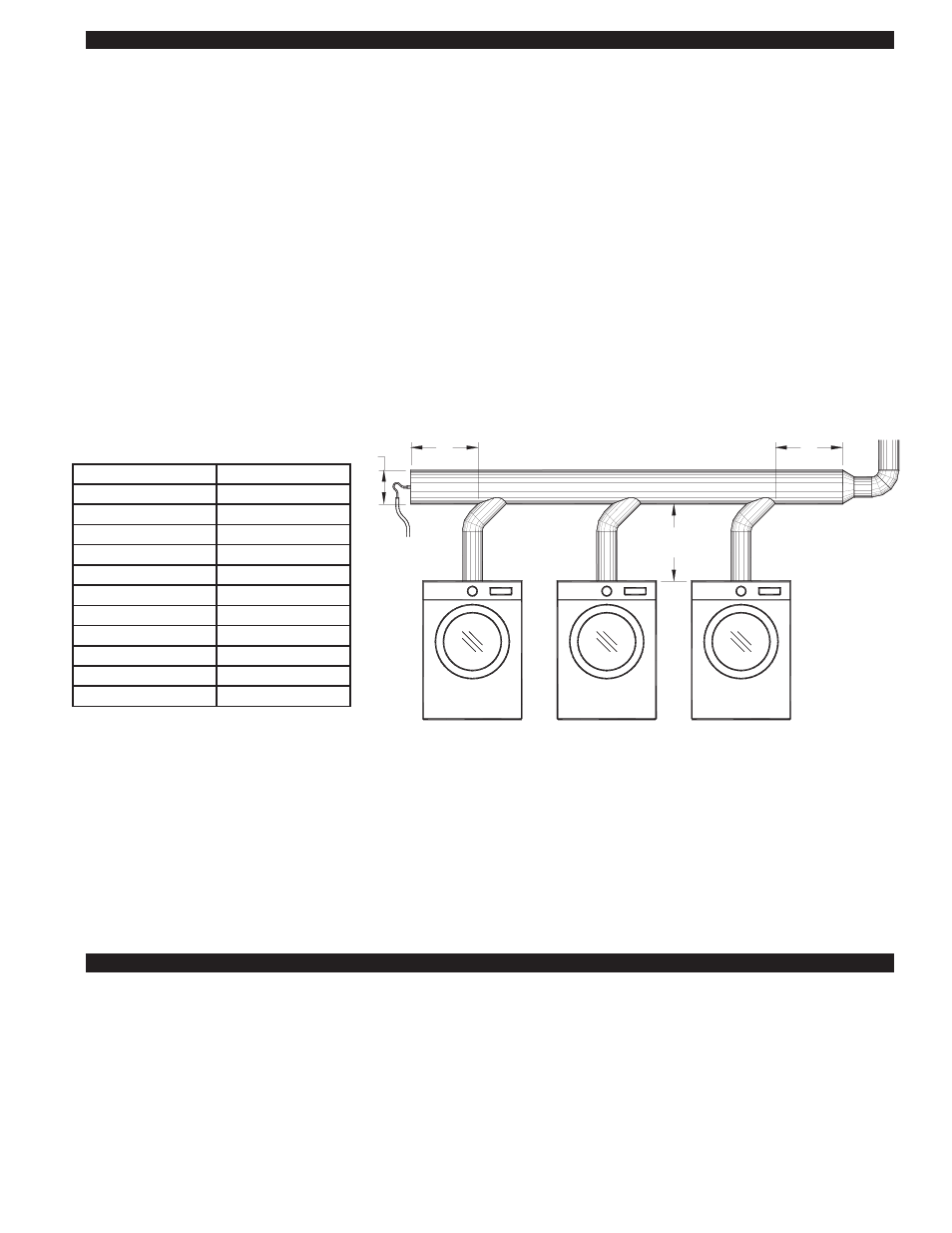
SIZING A COMMON VENT MANIFOLD SERVING MULTIPLE DRYERS
The most important step towards assuring that individual dryers vented into a common manifold exhaust smoothly is to size the
manifold large enough to reduce the affects that velocity in the manifold has on the junctions of the dryer vent connections.
Exhaust moving too quickly in a common vent manifold can amplify the exhaust at vent connectors by aspirating across the con-
nector opening and creating an amplified siphon affect. With a properly sized common vent manifold, velocities are maintained
below the point where they have a significant affect on the exhaust of the individual dryer connections.
It is important to note that these sizing recommendations are for the common vent manifold only and that the typically smaller mini-
mum vent diameter listed in the RT-Series Fan selection table may be used for the remainder of the horizontal vent and chimney.
The larger diameter vent manifold should extend at least 2 diameters beyond the last dryer connection point.
1. When in doubt, get help from Tjernlund Tech Service at 800-255-4208, push 0 and ask for technical assistance or email
[email protected] with details of the job.
2. When possible use 45
O
Manifold Tee connections to the common vent manifold in the direction of the RT-Series Fan instead of
90
O
Tee connections.
3. If possible, locate larger exhaust volume vent connections closer to the RT-Series Fan. This reduces the affect of their exhaust
on smaller volume connections.
4. The size of the common vent manifold should be at least 90% of the total area of all individual vent connections. See example
below.
Example: A vent layout is required for a job that consists of 3 dryers with 6” diameter outlets.
Add these areas together:
3 x 0.1964 = 0.5892
Total Area = 0.5892 Square Feet x 0.90 (90%) = 0.530. In looking at the table above, this area is greater than an 8" diameter pipe
but smaller than a 10" diameter pipe. 10" diameter vent is the minimum size the common vent manifold diameter should be. It is
perfectly acceptable to be larger than this area if desired. It is also acceptable to have this area be reduced as the vent system
works backward towards the appliance furthest from the RT-Series Fan. In this example, the common vent manifold should extend
at least 20" past the connection point of the dryer farthest from the RT-Series Fan.
XCOP1 INSTALLATION
Do not mount the XCOP1 junction box on a heat source that exceeds 140
O
F (60
O
C). Examples of improper mounting surfaces
include vent pipe, top of heater casing or any place where radiant or convective heat would cause the junction box temperature to
exceed 140
O
F (60
O
C). The XCOP1 is intended for indoor installation only.
Using the key hole slots on the back of the XCOP1 junction box as a template, mark 4 holes on the mounting surface, drill pilot
holes if necessary, and secure junction box using provided screws.
E
Breech Size Diameter Area (Square Feet)
3”
0.0491
4”
0.0873
5”
0.1364
6”
0.1964
8”
0.3491
10”
0.5454
12”
0.7854
14”
1.0690
16”
1.3960
18”
1.7670
20”
2.1820
D
2D
MINIMUM
2D
MINIMUM
COMMON VENT MANIFOLD
MAINTAIN THE DRYER
OUTLET DIAMETER UNTIL
THE COMMON MANIFOLD
FIGURE 8054009 4/14/11
DRYER FURTHEST
FROM THE INDUCER
SENSING TUBING
TO XCOP1
DRYER FURTHEST
FROM ROOFTOP FAN