Diagram c, Diagram d – Tjernlund CSA1 Chimney Stack Assist Kit 8504201 User Manual
Page 5
4
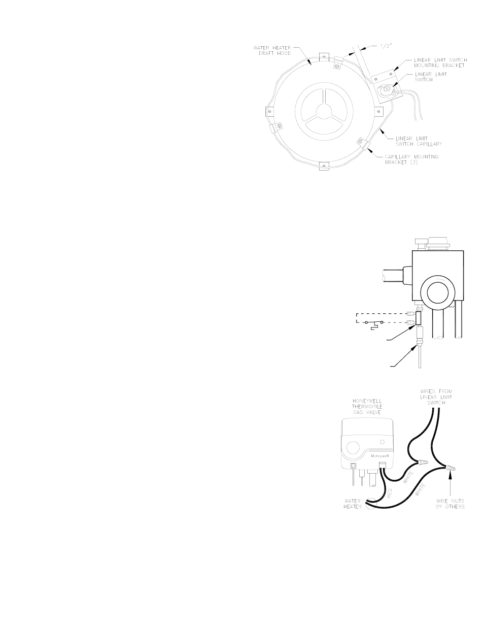
LINEAR LIMIT SPILLAGE SENSING SWITCH INSTALLATION
PURPOSE: To provide a means for appliance shut-down in the
event of flue blockage or CSA1 failure.
OPERATION: When concentrated spillage of the products of
combustion occurs from the draft hood, the Linear Limit Spillage
Switch circuit will open preventing burner operation.
1. Attach the Linear Limit sensing switch mounting bracket to the
top of the water heater using the 1/2” sheet metal screws
provided. The Linear Limit bracket should be approximately
1/2” from the draft hood.
2. Attach the three Linear Limit capillary mounting brackets
around the draft hood, equally spaced. Uses 3/8” screws.
3. Insert the Linear Limit spillage sensing switch capillary into
the “U” of the Linear Limit brackets outlining the perimeter of
the draft hood. The Linear Limit capillary may be overlapped.
if necessary, (See Diagram B). IMPORTANT: DO NOT CUT
THE CAPILLARY, it will be destroyed and water heater will be disabled.
4. Route the Linear Limit spillage sensing switch cable down the water heater casing locating the end near the Thermocouple or
E.C.O. of water heater. Secure it with the cable clamps and self drilling screws provided.
THERMOCOUPLE INSTALLATION
Unscrew the thermocouple from gas valve and screw in the Thermocouple Junction
Adapter. Screw the thermocouple into the Thermocouple Junction Adapter. Connect the
Linear Limit cables to the spade connections on the Thermocouple Junction Adapter, (See
Diagram C). NOTE: On 750 Millivolt (power pile) heaters, wire the Linear Limit Spill Switch
in series with the high limit (E.C.O.) of heater, see Thermopile installation below.
THERMOPILE INSTALLATION
Cut white wire from the thermopile gas valve and wire nut both ends with Linear Limit wires
(See Diagram D). Thermocouple Junction Adapter is not required for Thermopile installa-
tions.
T
O
H
N
O I
T
A
C
A
V
M
R
A
W
JUNCTION ADAPTER
THERMOCOUPLE
950-0470 (JA1)
LINEAR LIMIT
SPILL SWITCH
GAS
VALVE
THERMOCOUPLE
8050010 11/30/11
DIAGRAM C
DIAGRAM B
DIAGRAM D