Tjernlund CSA1 Chimney Stack Assist Kit 8504201 User Manual
Page 2
DESCRIPTION
The CSA1 Inducer assures draft in orpaned water heaters, oversized chimneys or when slight negative pressures in buildings prevent
proper exhaust of combustion gas. The venturi action of Tjernlund’s CSA1 Inducer starts air moving smoothly. These units are easy to
install and completely automatic in operation. Tjernlund’s unique design and durable construction makes them maintenance free.
IN THE EVENT OF PILOT OUTAGE
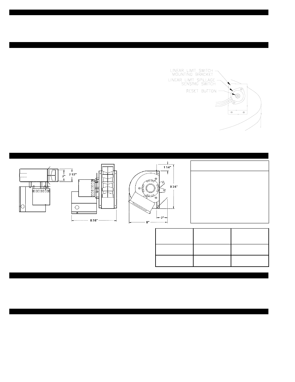
1. Push the reset button in the center of the Linear Limit Spillage Switch located
near the draft hood on the top of the water heater.
2. Follow water heater manufacturer’s re-lighting instructions attached to water
heater or located in water heater owner’s manual.
3. Turn the gas pilot knob at the top of water heater gas valve to “OFF” position.
WARNING: Gas pilot knob MUST REMAIN IN “OFF” POSITION FOR FIVE
MINUTES BEFORE PILOT IS RE-LIT. Perform steps 4 & 5 while waiting.
4. Visually verify that there is 115 volt power established to the CSA1.
Check fuse or circuit breaker, wall plug and electrical connections.
5. Visually verify that all electrical connections of control cord circuit are intact.
NOTE: Since the CSA1 cannot operate during a power outage, the safety interlock controls are designed to prohibit gas flow
to the water heater in the event of prolonged flue gas spillage. Follow the above procedures and water heater manufacturer’s instruc-
tions for relighting the pilot when power has been restored.
SPECIFICATIONS
Maximum BTU/hr. input rating of equipment: 65,000.
* NOTE: 3” 90 Degree elbows are equivalent to 3 feet.
4” 90 Degree elbows are equivalent to 4 feet.
TOOLS NEEDED
1/4” Nut Runner
11/32” Nut Runner
Tin Snips
Drill
Gas Pipe Tape
High Temp Silicone
1/4” Tube/Pipe Cutter
Drill Bit Set
7/16” Open End Wrench
3/8” Open End Wrench
1/2” Open End Wrench
SEQUENCE OF OPERATION
1. Water heater thermostat calls for heat.
2. CSA1 activates and the burner fires simultaneously.
3. Burner & CSA1 shut down simultaneously when thermostat is satisfied.
If sustained flue gas spillage is detected by the Linear Limit Spillage Switch the Water Heater Safety Circuit is opened and pilot light is
extinquished. The Linear Limit spillage switch must be reset and the pilot relit to reestablish burner operation.
1
MOTOR SPECIFICATIONS
ELECTRICAL DATA
Volts
115
Hertz
60
RPM
1550
Watts
35
Amps
.43
Therm. Prot.
Imp. Prot.
Pipe Diameter
Water Heater
Capacity
Max. Equivalent*
Horizontal Vent
Connector Length
3”
Up to
45,000 BTU/hr
15 feet
4”
Up to
65,000 BTU/hr
20 feet