Warning – Tjernlund CSA1 Chimney Stack Assist Kit 8504201 User Manual
Page 3
INSTALLATION RESTRICTIONS
WARNING
Failure to install, maintain and/or operate the CSA1 in accordance with manufacturer's instructions may result in conditions
which can produce bodily injury and property damage.
The CSA1 must be installed by a qualified installer in accordance with these instructions and all local codes or in their
absence in accordance with the latest editions of The National Fuel Gas Code (NFPA #54), Chimneys, Fireplaces, Vents, and
Solid Fuel Burning Appliances (NFPA 211), and the Occupational Safety and Health Act (OSHA) when applicable. Improper
installation can create a hazardous condition such as an explosion, fire, electrical shock or carbon monoxide poisoning
resulting in property damage, personal injury or death.
1. The CSA1 shall not be used on condensing heating equipment.
2. Gas-fired units without a draft hood / diverter must include a barometric draft regulator.
3. The CSA1 motor shaft must be mounted horizontally to prevent motor bearing wear.
4. The CSA1 shall not be installed where flue gas temperatures exceed 575
O
F (301°C) at the CSA1 inlet. Ambient room temperatures
must not exceed 104° F (40° C).
5. The installer must affix the wiring diagram label included with these instructions to the water heater casing adjacent to its rating plate.
6. The water heater may only be installed on the suction side of CSA1.
7. The installer must verify that the pilot safety controls on the water heater are in good operating condition before installation of the
water heater vent package.
8. The CSA1 must not be installed into any portion of a vent system which serves appliances other than the one vented by the CSA1.
9. Make certain the power source is adequate for the fan motor requirements. Do not add the CSA1 to a circuit where the total load is
unknown.
10. The installer must verify that the BTU/hr input of the water heater does not exceed the maximum input rating of the CSA1 (65,000 BTU/hr).
11. A safety inspection of the water heater must be performed before installation of the CSA1 as outlined in the International Fuel Gas
Code, (IFGC) Appendix D.
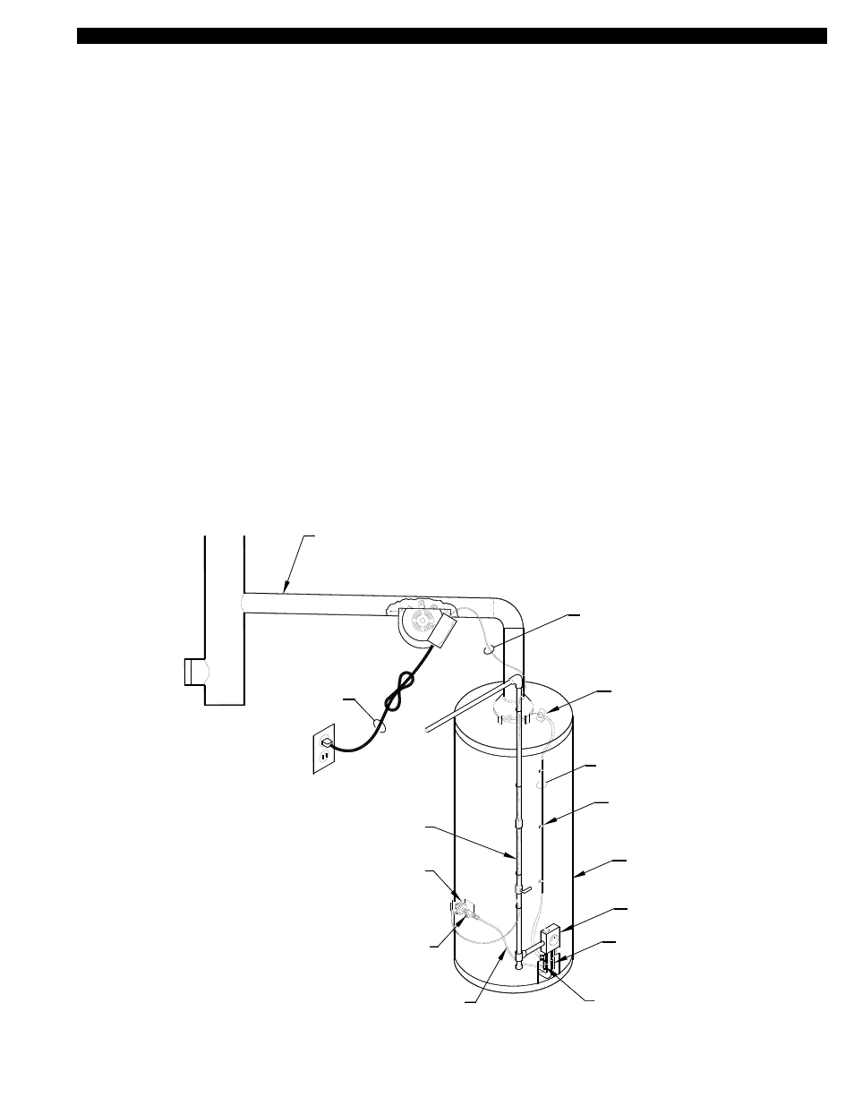
2
WITH THE ECO OF THE WATER HEATER.
REQUIRED. WIRE THE LINEAR LIMIT IN SERIES
THE THERMOCOUPLE JUNCTION ADAPTER IS NOT
ON 750 MILLIVOLT (POWER PILE) HEATERS
THERMOCOUPLE JUNCTION ADAPTER
PRESSURE TAP
FROM THERMOSTAT
6' LINEAR
LIMIT LEADS
115/1/60
SWITCH
GAS PRESSURE
GAS PRESSURE SWITCH
ALUMINUM TUBING TO
24" LONG 1/4" O.D.
LINE
GAS SUPPLY
BY OTHERS
WATER HEATER
BY OTHERS
THERMOSTAT
LINE
GAS PILOT
8050049 04/18/13
CLIPS
ROUTING
CABLE
THERMOSTAT CABLE
2 WIRE JACKETED
POWER CORD
SWITCH SET AT 185°F
SPILLAGE SENSING
LINEAR LIMIT
NEW GAS PRESSURE
TAP PORT LOCATION
NOTE:
CSA1
CAP ANY UNUSED
1/4 INCH PER FOOT
TOWARDS CHIMNEY
SLOPE UPWARD
- KEEP AWAY FROM
THE HOT FLUE PIPE
STACK OPENINGS
6 FOOT