Operation procedures – Symtech LCA2 EZ User Manual
Page 6
6
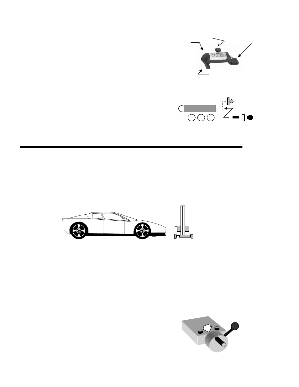
The laser is used for floor slope measurement only. Remove
laser after floor slope measurements have been recorded
Remove floor slope laser from packaging and insert front
fixture placement pin into hole on top and at front of the
optical head, also there is an indentation provided for the
height adjustment screw to rest within.
Activate the laser by turning ON/OFF knob clockwise
(CAUTION: Excessive turning may damage laser
ON/OFF mechanism) to assure of functionality, turn off
laser. No further adjustment is required.
NOTE: Should calibration of the laser become necessary in
the future, Refer to “LASER CALIBRATION”.
Calibration, Section 5.1, Pg. 9.
Laser Battery Replacement
Unscrew back of laser and replace batteries with three (3), LR 44
button batteries. Reverse process for assembly.
After battery replacement, CALIBRATION REQUIRED.
3. OPERATION PROCEDURES
3.1 PREPARATION, ALIGNMENT BAY(s)
Prior to any headlamp alignment using the LCA 2
EZ
, the floor slope of the bay, or bays must be
determined, this is done by using the floor slope laser assembly and noting the position of the rear floor slope
wheel.
If the correct floor slope of the bay is not adjusted prior to any headlamp alignment, the technician will align
the headlamps in a higher, or lower position than what is correct. The LCA 2
EZ
must be on the same
plain as the vehicle that is to be aligned, if the vehicle is positioned on a floor that has an upward slope
running from fore to aft of vehicle, then the LCA 2
EZ
must be adjusted to have the same slope.
3.2 FLOOR SLOPE MEASUREMENT
Tool Required: Tape Measure or Ruler
Move the LCA 2
EZ
to the service bay to be used for headlamp alignment and place the LCA 2
EZ
at
the front of the vehicle, off to one side. If multiple bays are to be used, procedure for determining floor slope
will need to be performed in each bay and recorded.
Lower the optical head to the bottom of the mast. Adjust optical head by rotating eccentric wheel at rear of
base until level vial registers level. Turn the laser on with the thumbscrew on the front of the laser assembly.
At the center point of the front wheel of the vehicle measure the distance from the floor to the point where the
laser strikes the tape measure, RECORD.
Move to the center point of the rear wheel of vehicle and measure the point where the laser strikes the tape
measure, RECORD.
If the measurements at the front and rear wheels are
not equal, the bay has a slope.
Rotate the floor slope handle on rear wheel until equal
measurements are registered at the front and rear wheels.
NOTE: When rotating eccentric axle on LCA 2
EZ
, both
measurements will change at front and rear vehicle
On / Off
Knob
Level Adjuster
Set Screw
Fixture
Placement Pin
ON/OFF
Knob
LR44
LR44
LR44