Assembly – Symtech LCA2 EZ User Manual
Page 4
4
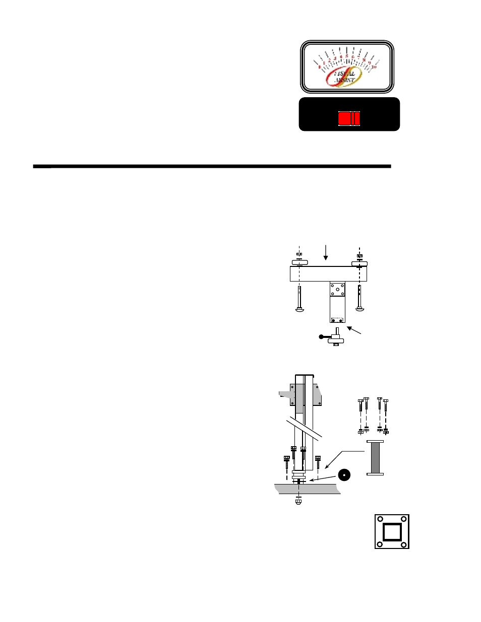
1.4 VISUAL ASSIST METER & SWITCH
The “Visual Assist” meter is an aide for positioning the headlamp
pattern to its correctly designed position. While visually adjusting
the headlamp into position, the “Visual Assist” meter will raise in
numeric reading if adjustment is directed in the correct direction.
Adversely, the meter reading will decrease if headlamp is adjusted in
the incorrect direction. When the highest achievable reading is
attained both vertically and horizontally, the headlamp will be
positioned correctly.
The SELECTOR switch moves the “Visual Assist” meter function
between High and Low Beam patterns. Make sure that the switch is
in the correct location for the beam pattern to be aligned.
2. ASSEMBLY
Inspect all components of the LCA 2
EZ
system to assure that no damage has occurred during shipment, compare
contents of package with that of the exploded view to make sure that no component has been inadvertently left out of
packaging. If a component is missing, contact our customer service department at 888-884-8182 for an immediate
replacement.
2.1 BASE / WHEEL ATTACHMENT
Place base of system on floor, or table with channel facing
downward.
Insert a 5/16” x 6” carriage bolt into each of the holes noted, making
sure that the square carriage bolt head seats securely into the square
hole placement.
Complete wheel assembly by placing in order a large nylon washer,
wheel, small nylon washer and self-locking 5/16” nut on carriage
bolt.
Tighten self-locking nut snug against wheel, but not so tight as to
hinder free wheel movement.
Insert floor slope eccentric and wheel into mounting block on base
(rear wheel). Tighten friction bolt until floor slope eccentric can be
moved, but not loose enough to move by itself.
2.2 MAST / GLIDE PLATE / ROTATIONAL MAST MOUNT
The Mast, Counterweight Spring Cover, Spring and Glide Plate are
packaged as an assembly.
Remove tie-lock band from base of mast, attach rotational mast
mount to mast with four (4)
5
/
16
” x ¾” bolts and tighten securely,
making note of bolt tightening sequence.
Place rotation bearing over mast stud and insert rotational mast stud
into base. Secure mast to base with
1
/
2
” flat washer and ½” self-
locking nut. Tighten nut securely then back-off ¼ turn, or until
mast rotates freely with minor resistance.
NOTE: Do not incorporate the mast extender in the assembly, if
alignment of vehicle headlamps over 45” in height are not
expected to be assessed. Majority of vehicles will fall
under the 45” allowance, FACT: MOST OVER THE
ROAD TRUCKS and SUV’s FALL UNDER THE 45”
HEADLAMP HEIGHT.
Move glide plate up and down the mast through its full motion, by
depressing handle.
NOTE: if glide plate moves without tension felt from the spring, it
is possible that the spring has dislodged during shipment.
It will be necessary to remove the mast spring cover and
reattach the glide plate spring.
1
3
4
2
TIGHTENING
SEQUENCE
“HIGH”
BEAM
“LOW”
BEAM
VISUAL ASSIST
SELECTOR
Tighten
this Bolt
Front of Base
ROTATIONAL
BEARING