Symtech LCA2 EZ User Manual
Page 5
5
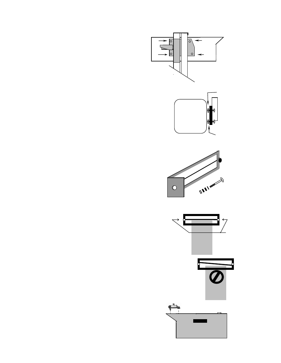
2.3 OPTICAL ALIGNMENT HEAD
Remove optical alignment head from shipping carton.
Inspect for any damage that may have occurred during
shipment i.e. lens, case, etc..
Attach optical alignment head to the mast glide plate by
aligning mounting holes of glide plate with the holes in
the optical head. Insert ¼” x 20 x ¾” allen head machine
screws through glide plate, place a ¼” x
1
/
8
” (WHITE)
nylon spacer on each upper attachment screw, place a ¼”
x ¼” (BLACK) nylon spacer on each lower attachment
screw, attach optical head and tighten securely.
Remove protective paper covering from viewing window
on top of optical head.
Move optical head through the full range of movement to
assure of smooth operation.
2.4 SIGHTING UNIT
Sighting unit is the “L” bracket assembly enclosed
in the accessories box.
NOTE: Mount sighting unit so that unit is
located directly over the optical head.
Insert the
5
/
16
” x 3” slotted head machine screw with
5
/
16
” nylon washer into the sighting unit.
Place a small nylon bushing on the screw and insert
screw through the holes provided at the top of the
mast, place two large nylon bushing on screw, sight
unit, and self-locking nut.
Tighten to a tension that allows for movement of
sighting unit, but provides sufficient friction to hold
unit in place when unattended.
NOTE: Sighting unit must be calibrated to the optical head prior
to alignment of headlamps.
2.5 SIGHTING UNIT CALIBRATION
Calibration of sighting unit must be performed prior to alignment of
headlamps.
Raise optical head of LCA 2
EZ
to the approximate center of
travel of mast.
Turn the sighting unit until you can see the front edge of the optical
head while looking through the sighting unit lens. Line on lens
should line up with the front edge of the optical head.
If line does not line up with the front edge of optical head, loosen
the thumbscrews on the lens and move the lens into alignment.
Tighten thumbscrews.
It is important that periodical checking of calibration of the sighting
unit be performed, to assure customer satisfaction.
NOTE: When technicians of differing heights are using the LCA
2
EZ
and the sighting unit is rotated for better viewing,
the sight unit must be checked for calibration and
adjustment made accordingly.
2.6 FLOOR SLOPE LASER
The floor slope laser assembly is factory calibrated, DO
NOT turn the level adjustment set screw.
Optical
Head
IN
Calibration
OUT of
Calibration
Adjustment
Thumb Screws
Optical
Head
¼” x 20 x ¾”
Allen head
Glide
Plate
Optical
Head
¼” x
1
/
8
”
Nylon Spacers
(WHITE)
¼” x ¼”
Nylon Spacers
(BLACK)