Stack-frame-assy, Stack system anchoring, Stack frame assembly and installation – Oldcastle BuildingEnvelope FG-2000 User Manual
Page 12
STACK FRAME ASSEMBLY AND INSTALLATION
The assembly and sealant procedures are a part of the installa-
tion sequence because of the stacking method.
HEAD CAN:
Anchor screws should be within 4" of each side of the intended
mullion location. Head anchors (AC-109-1 PART #: 6554) should
be used if the height x width x design load is 500 lbs. or more at
the top of the mullion. Normally one anchor screw at the middle
of the lite or 24" O.C. is adequate for securing the header. For
unusual conditions, consult
™
engineering department.
SILL CAN:
Shim can a minimum
1
⁄
4
". Anchor sill can 24" O.C. and no more
than 4" on each side of intended mullion locations. Be sure
weeps are located under center line of mullion. Seal both sides
of can.
HORIZONTAL HEAD AND SILL INSERTS:
Members are cut
1
⁄
16
" less than daylight opening to allow for
incremental expansion.
JAMB MEMBERS:
Remember all horizontals are cut 1/16" short. Do not over shim
between jamb and structure.
MULLIONS:
Cut mullion length outside frame dimension minus 1
8
". Install mulls
1/
by sliding top end over anchor and rotating bottom into position.
RECOMMENDATION:
Prior to glazing, fill sill cavity with water to assure that end dams
and anchors are sealed.
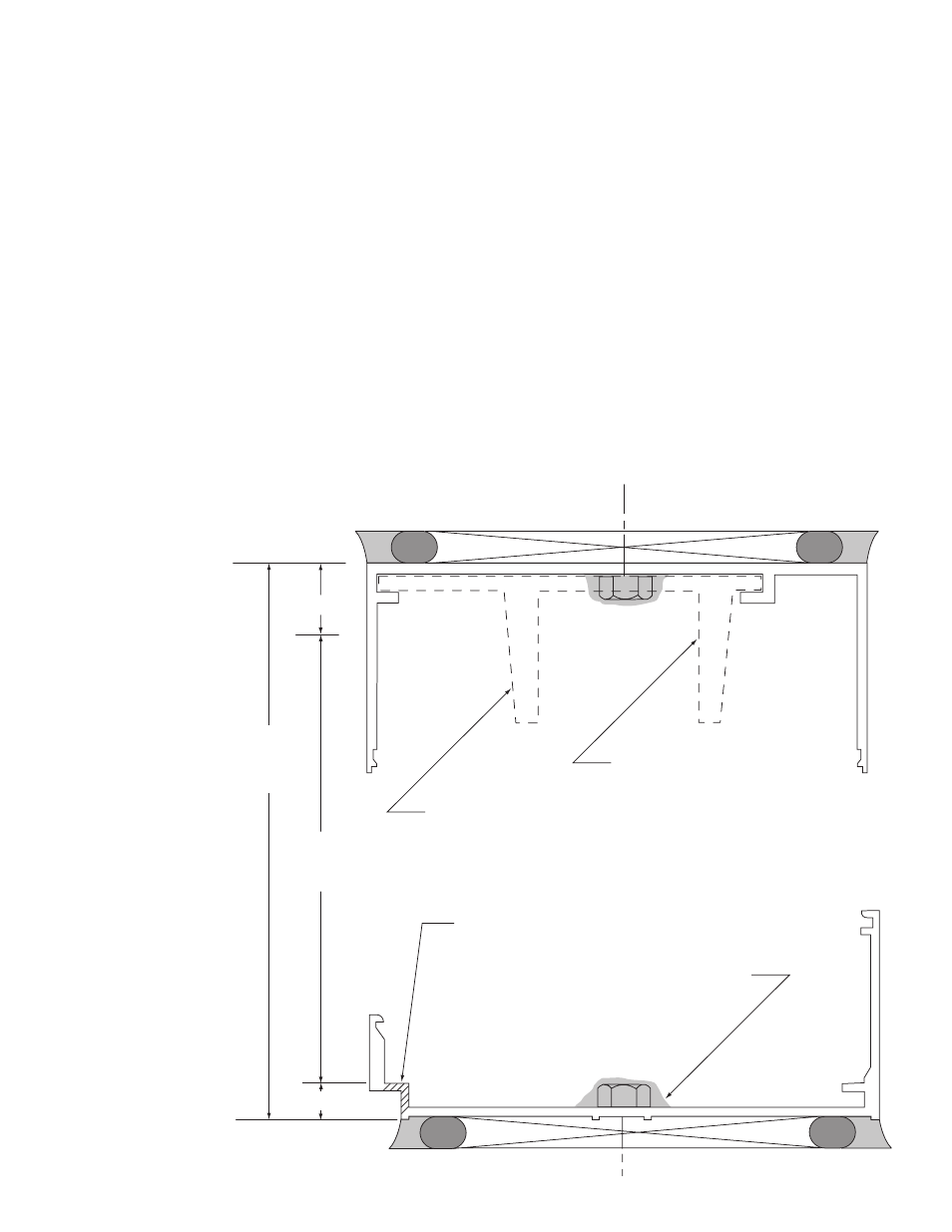
STACK SYSTEM
ANCHORING
AC-109-1 PART #: 6554
MULLION ANCHOR ROTATES
INTO HEAD CAN.
1/4" DIA. WEEP HOLE AT CENTER
LINE OF INTERMEDIATE MULLIONS.
CAP SEAL ALL HEAD AND
SILL CAN ANCHORS.
-3/4"
3/8"
MULLION
HEIGHT
FRAME
DIMENSION
11
FEBRUARY 2012
F L U S H G L A Z E S E R I E S 1 0 0 0 a n d 2 0 0 0 I N S T A L L A T I O N M A N U A L