27_expansion_mullion – Oldcastle BuildingEnvelope 6000 Series Thermal MultiPlane User Manual
Page 28
27
S E R I E S 6 0 0 0 T H E R M A L M U L T I P L A N E I N S T A L L A T I O N M A N U A L
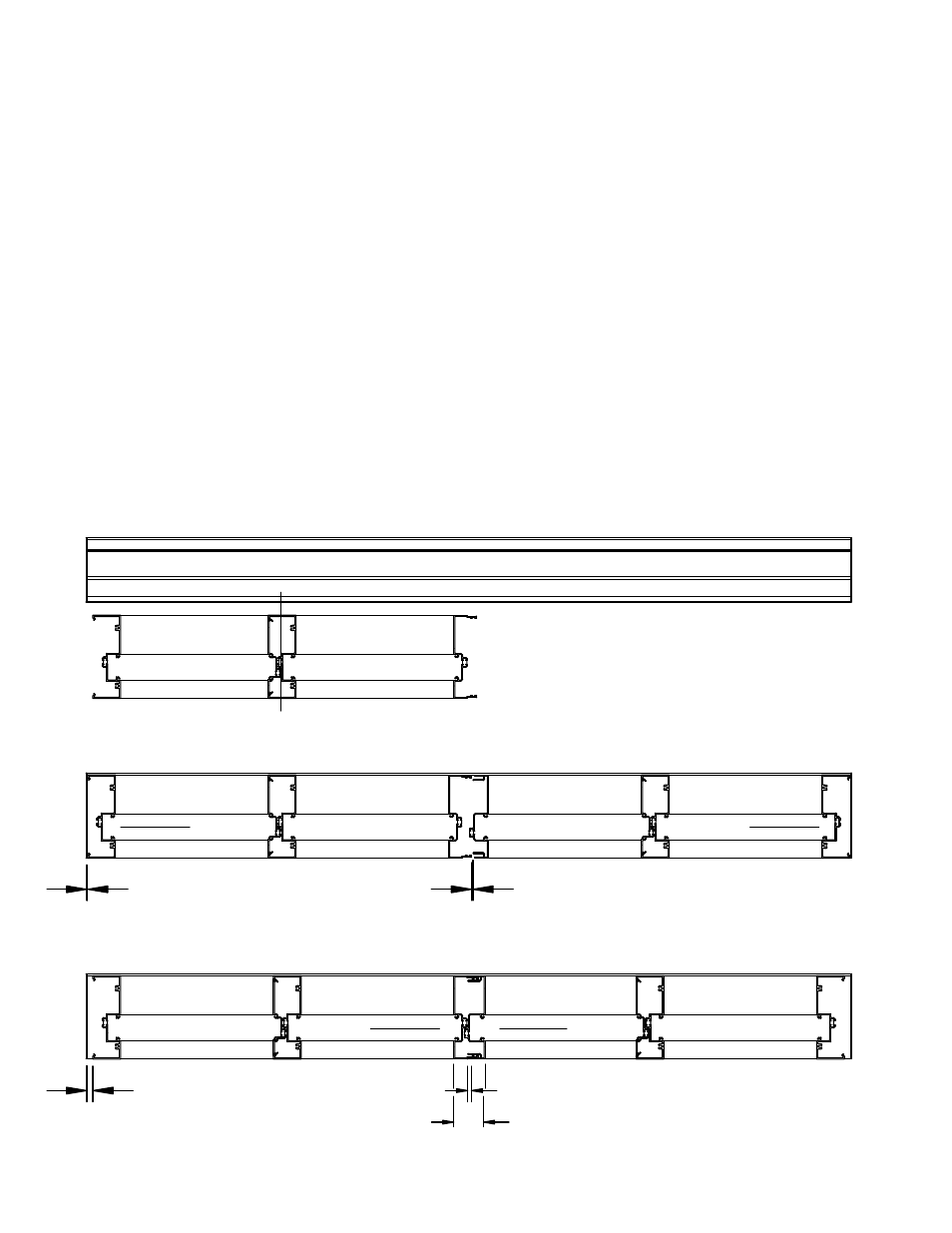
EXPANSION MULLION INSTALLATION
7/16"
1/4"
1/16"
3/8"
3/8"
The example below shows installation of the center
set system, options for front or back set are also
available. Please reference price catalog for specific
extrusions and anchors required for your installation.
Please note the locations of various seals and insure
proper locations of these seals when installing typical
runs and expansion sections of each of these
systems. These seals are shown in the sub-sill
installation and assembly sections of this manual.
The sub-sills for these products are designed so
that sill anchors may be properly sealed prior to
frame installation. The frame is either installed over
the hook-in anchors or dropped into the sill receptor.
This prevents any additional fasteners from
penetrating the sill and potentially causing leaks
from under the sill. Be sure to properly cap seal all sill
anchors prior to beginning installation of frames.
Multiple units may require the use of an expansion
mullion if total run exceeds 24 feet in length. When
elevation exceeds the 24 foot limit, locate thermal
mullions at a distance of no more than every 20 feet.
Locate splice in sub-sill at a distance of no more than
every 12 feet. A minimum of 7/16" clearance between
the jamb and sill end dam must be provided at each
end of units when using expansion mullions. This will
allow the minimum 3/8" clearance to move the units
sideways so that the second unit may be rotated into
position and interlocked into first unit. Once in
position units should be centered into opening to
provide equal joints at the jambs. Oldcastle
BuildingEnvelope recommends the use of the
FG-6188 PVC filler in the jambs and head to improve
the perimeter seal.
1/4"
2 1/4"
TM