2 front panel, Front panel - 7, Am5010 introduction – Kontron AM5010 User Manual
Page 25
AM5010
Introduction
ID 1022-1107, Rev. 4.0
Page 1 - 7
P R E L I M I N A R Y
1.4.2
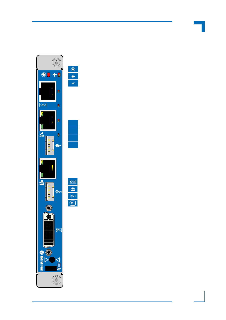
Front Panel
Figure 1-2:
AM5010 Front Panel
AM5010
0
1
2
3
For further information on the LEDs used on the AM5010, refer to Chapter
2.3.1, “Front Panel LEDs”.
LED1 (red):
Out-of-Service LED
LED2 (red/green/amber): Health LED
HS LED (blue):
The hot swap indicator provides basic
feedback to the user on the hot swap
state of the module. The HS LED states
are off, short blink, long blink, and on.
Module LEDs
ULED3 (red/green):
AMC Eth. port A link signal status or
BIOS POST code LED
ULED2 (red/green):
AMC Eth. port B link signal status or
BIOS POST code LED
ULED1 (red/green):
Freely configurable or BIOS POST
code LED
ULED0 (red/green):
Freely configurable or BIOS POST
code LED
User-Specific LEDs
3
2
1
0
Serial Connector
Gigabit Ethernet Connector
USB Connector
DVI-I Connector
Connectors
- CP3003-SA uEFI BIOS (72 pages)
- CP3003-SA (36 pages)
- CP3002 (38 pages)
- CP3002-RC uEFI (64 pages)
- CP-RIO3-05 (42 pages)
- CP3002-RC (30 pages)
- CP342 (52 pages)
- CP930 (46 pages)
- CP932 (52 pages)
- CP346 (72 pages)
- CP384 (66 pages)
- CP383 (74 pages)
- CP382 (58 pages)
- CP381 (60 pages)
- CP372 (64 pages)
- CP371 (60 pages)
- CP-RIO3-04S (38 pages)
- CP390 (36 pages)
- CPS3410 (9 pages)
- CPS3402 (9 pages)
- CPS3105 (9 pages)
- CPS3101 (9 pages)
- CPS3003-SA (19 pages)
- PB-SIO4 (34 pages)
- PB-SIO4A (34 pages)
- PB-DOUT8 (34 pages)
- VMOD-2 (82 pages)
- VSBC-32 (110 pages)
- VM42 (62 pages)
- Bootstrap Loader (24 pages)
- VMP1 with Netbootloader (120 pages)
- VMP1 (106 pages)
- NetBootLoader (86 pages)
- VMP2 (142 pages)
- VMP3 (154 pages)
- CP-RIO6-923 (32 pages)
- CP-RIO6-923-F (32 pages)
- CP-RIO6-001 (28 pages)
- CP-RIO6-001-HD-VGA (46 pages)
- CP-RIO6-M (20 pages)
- CP-RIO6-B (28 pages)
- CP6925 (42 pages)
- CP6002 uEFI BIOS (76 pages)
- CP6002 IPMI (40 pages)
- CP6002 (42 pages)