At8901m hardware description – Kontron AT8901M User Manual
Page 50
AT8901M
Hardware Description
Page 3 - 20
AT8901M User Guide
The LED number on the front plate indicates the logical ATCA slot (not the channel number) of
the connection. LED 1 for the base interface is the combined status/activity LED for both ShMC
links. If any of the two ShMC links is up, the LED is lit. If any of the links is active, the LED blinks.
Each RJ45 displays the status of the link with the two integrated LEDs.
The reset switch will perform a reset on the CPU when pressed for less than 1 second and a
complete board reset (including IPMI) when pressed for more than 2 seconds.
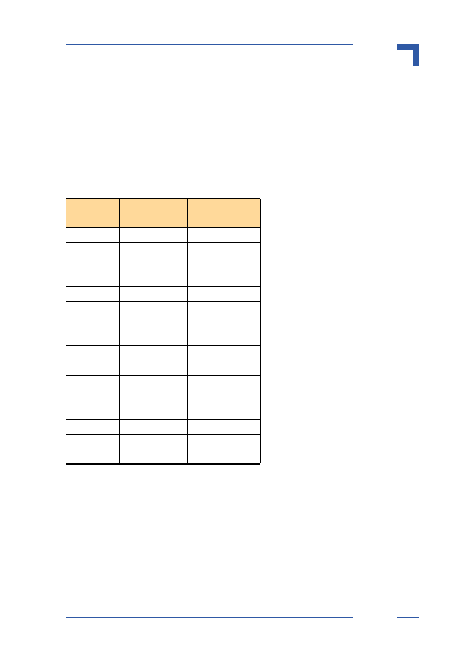
Switch LED Assignment
Table 3-19: Switch LED Assignment
Switch LED
Number
Base Interface
Logical ATCA
Slot
1
SMCA/B (Ch 1)
ShMC (s)
2
Ch 2
(other Hub)
3
Ch 3
3
4
Ch 4
4
5
Ch 5
5
6
Ch 6
6
7
Ch 7
7
8
Ch 8
8
9
Ch 9
9
10
Ch 10
10
11
Ch 11
11
12
Ch 12
12
13
Ch 13
13
14
Ch 14
14
15
Ch 15
15
16
Ch 16
16
- CP3003-SA uEFI BIOS (72 pages)
- CP3003-SA (36 pages)
- CP3002 (38 pages)
- CP3002-RC uEFI (64 pages)
- CP-RIO3-05 (42 pages)
- CP3002-RC (30 pages)
- CP342 (52 pages)
- CP930 (46 pages)
- CP932 (52 pages)
- CP346 (72 pages)
- CP384 (66 pages)
- CP383 (74 pages)
- CP382 (58 pages)
- CP381 (60 pages)
- CP372 (64 pages)
- CP371 (60 pages)
- CP-RIO3-04S (38 pages)
- CP390 (36 pages)
- CPS3410 (9 pages)
- CPS3402 (9 pages)
- CPS3105 (9 pages)
- CPS3101 (9 pages)
- CPS3003-SA (19 pages)
- PB-SIO4 (34 pages)
- PB-SIO4A (34 pages)
- PB-DOUT8 (34 pages)
- VMOD-2 (82 pages)
- VSBC-32 (110 pages)
- VM42 (62 pages)
- Bootstrap Loader (24 pages)
- VMP1 with Netbootloader (120 pages)
- VMP1 (106 pages)
- NetBootLoader (86 pages)
- VMP2 (142 pages)
- VMP3 (154 pages)
- CP-RIO6-923 (32 pages)
- CP-RIO6-923-F (32 pages)
- CP-RIO6-001 (28 pages)
- CP-RIO6-001-HD-VGA (46 pages)
- CP-RIO6-M (20 pages)
- CP-RIO6-B (28 pages)
- CP6925 (42 pages)
- CP6002 uEFI BIOS (76 pages)
- CP6002 IPMI (40 pages)
- CP6002 (42 pages)