10 display elements, 10 display elements - 18, At8901m hardware description – Kontron AT8901M User Manual
Page 48: Amc 1 mid- size amc 2 mid- size
AT8901M
Hardware Description
Page 3 - 18
AT8901M User Guide
3.10
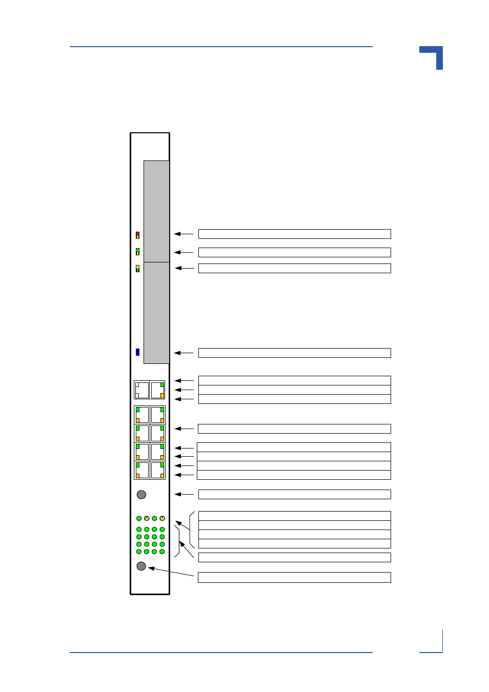
Display Elements
Figure 3-3: AT8901M Front Panel
Push Button (Not Used)
Switch LEDs display Link (on) and Activity (blink)
USER LED2 displays Base Switch LEDs selected.
USER LED4 (Not Used)
USER LED1 displays Base Switch error (red), initiation (yellow), operational (green) .
USER LED3 (Not Used)
B4
B2
B3
B1
AMC
1
Mid-
size
AMC
2
Mid-
size
CPU FE Port: LED (amber) displays Speed, Off 10Base-T, Blink 100Base-T
CPU FE Port: LED (green) displays Link (on) and Activity (blink)
Base Port 1/2: LED (green) displays Link (on) and Activity (blink)
Base Port 1/2: LED (amber) displays Speed, Off: 10Base-T, Blink: 100Base-T, On: 1000Base-T
Base Port 3/4: LED (green) displays Link (on) and Activity (blink)
Base Port 3/4: LED (amber) displays Speed, Off: 10Base-T, Blink: 100Base-T, On: 1000Base-T
Reset Push Button: (IPMC reset, Payload Power down)
RS-232 Interface: No LEDs
ATCA LED1 (red/amber) displays "Out of Service" (PPC/FWUM)
ATCA LED3 (amber/green) User defined
ATCA BLUE (blue) displays "Ready for Hot Swap" (IPMC)
ATCA LED2 (green/amber) displays "Healthy" (PPC/IPMC)
1
2
3
4
1
2
4
3
5
6
8
7
9
1
0
1
2
1
1
13 14
16
15
FE
RS232
Fabric Uplink (Not Used)