At8901m hardware description – Kontron AT8901M User Manual
Page 49
AT8901M
Hardware Description
Page 3 - 19
AT8901M User Guide
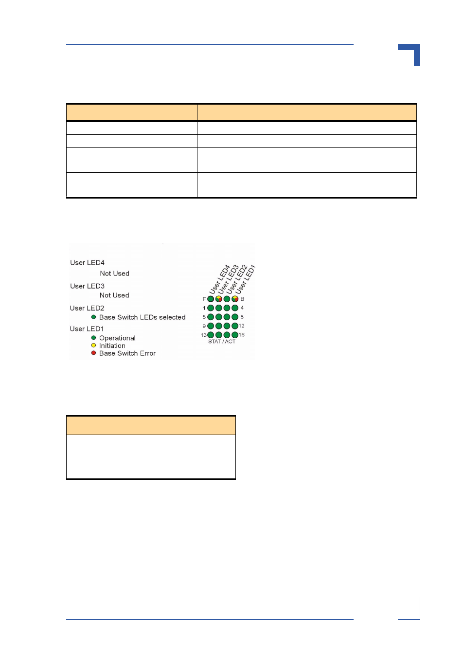
Figure 3-4: Backplane Switch LEDs Signification
Table 3-18: Backplane Link LEDs Signification
The four front panel ATCA LEDs (ATCA LEDs 1 to 3 and the Blue LED alongside the AMC slots)
display the board’s health and hotswap status (see table 3-17). LED1 of the User LEDs (see
figure 3-4) and the 16 STAT/ACT LEDs give status information for the base switch and its links.
User LED2 is always lit. The other two User LEDs and the LED push button do not have any
function.
Table 3-17: ATCA LEDs Signification
LED
Signification
ATCA LED3 (HB) (amber/green)
User definable
ATCA LED2 (HY) (green/amber)
On=Healthy (PPC/IPMC), Blink=Sensor out of range
ATCA LED1 (OOS) (red/amber)
On=Out of Service (PPC/FUM)
Blink=Firmware Update in Progress or Power denied
ATCA BLUE LED (H/S)
On=Ready for Hot Swap (IPMC)
Blink=Hot Swap in Progress
STAT/ACT LEDs 1-16
OFF
Link Down
ON
Link Up and no activity
BLINK
Link Up and activity
- CP3003-SA uEFI BIOS (72 pages)
- CP3003-SA (36 pages)
- CP3002 (38 pages)
- CP3002-RC uEFI (64 pages)
- CP-RIO3-05 (42 pages)
- CP3002-RC (30 pages)
- CP342 (52 pages)
- CP930 (46 pages)
- CP932 (52 pages)
- CP346 (72 pages)
- CP384 (66 pages)
- CP383 (74 pages)
- CP382 (58 pages)
- CP381 (60 pages)
- CP372 (64 pages)
- CP371 (60 pages)
- CP-RIO3-04S (38 pages)
- CP390 (36 pages)
- CPS3410 (9 pages)
- CPS3402 (9 pages)
- CPS3105 (9 pages)
- CPS3101 (9 pages)
- CPS3003-SA (19 pages)
- PB-SIO4 (34 pages)
- PB-SIO4A (34 pages)
- PB-DOUT8 (34 pages)
- VMOD-2 (82 pages)
- VSBC-32 (110 pages)
- VM42 (62 pages)
- Bootstrap Loader (24 pages)
- VMP1 with Netbootloader (120 pages)
- VMP1 (106 pages)
- NetBootLoader (86 pages)
- VMP2 (142 pages)
- VMP3 (154 pages)
- CP-RIO6-923 (32 pages)
- CP-RIO6-923-F (32 pages)
- CP-RIO6-001 (28 pages)
- CP-RIO6-001-HD-VGA (46 pages)
- CP-RIO6-M (20 pages)
- CP-RIO6-B (28 pages)
- CP6925 (42 pages)
- CP6002 uEFI BIOS (76 pages)
- CP6002 IPMI (40 pages)
- CP6002 (42 pages)