2 power distribution, Power distribution - 15, At8901m hardware description – Kontron AT8901M User Manual
Page 45
AT8901M
Hardware Description
Page 3 - 15
AT8901M User Guide
3.7.2
Power Distribution
The 48 Volts are supplied by the backplane via two independent rails, primary (A) and second-
ary (B). The rails are mixed using power Schottky rectifiers. A 7A fuse protects each -48V line
and a 10A fuse protects each RTN line. A hot swap controller enables the 48V power to the
board.
A quarter brick DC/DC converter transforms the 48 Volts to secondary 12 Volts, which are dis-
tributed on the board. The converter allows a maximum of 14A output current.
Two different management voltages (3.3V and 5V) and five payload voltages (3.3V, 2.5V, 1.8V,
1.25V and 1.2V) are generated by point of load converters. These are either switches or linear
regulators.
The management (or suspend) power is present once the board is connected to the backplane.
It supplies the IPMI part which in turn controls the payload power. The various payload voltages
are sequenced. The initial power up sequence is as follows (20ms delay between steps):
1. 3.3V, 1.8V and fabric mezzanine
2. 2.5V, 1.25V and 1.2V
The Power Down Sequence is performed in reversed order with a 1ms delay.
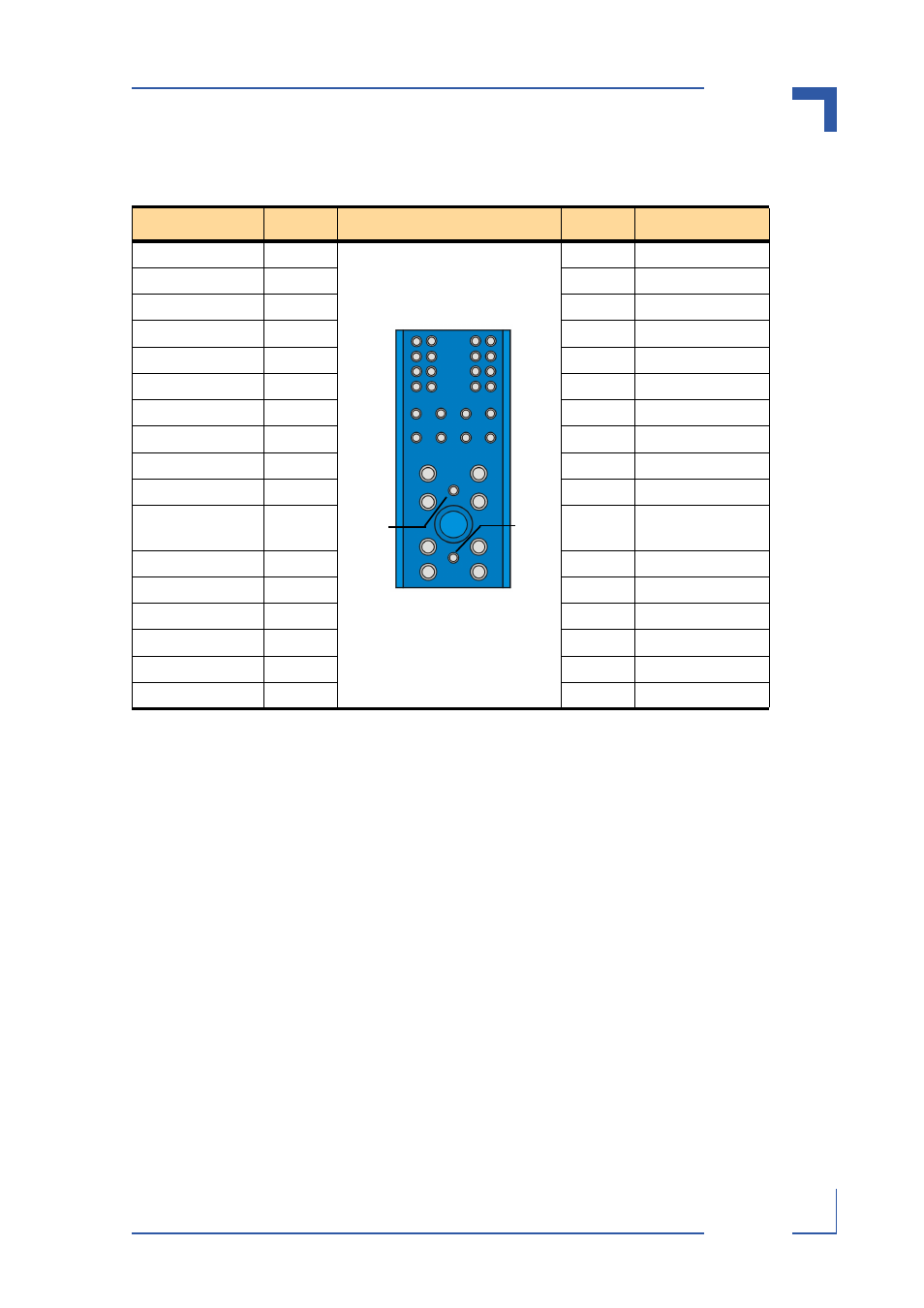
Table 3-14: Power Connector (P10)
Signal
Pin
Pin
Signal
N.C.
1
2
N.C.
N.C.
3
4
N.C.
HA0
5
6
HA1
HA2
7
8
HA3
HA4
9
10
HA4
HA6
11
12
HA5
SCL_A
13
14
SDA_A
SCL_B
15
16
SDA_B
MT1_TIP(N.C.)
17
18
MT2_TIP(N.C.)
RING_A(N.C.)
19
20
RING_B(N.C.)
MT1_RING(N.
C.)
21
22
MT2_RING(N.
C.)
RRTN_A(N.C.)
23
24
RRTN_B(N.C.)
SHELF_GND
25
26
LOGIC_GND
ENABLE_B
27
28
VRTN_A
VRTN_B
29
30
EARLY_A
EARLY_B
31
32
ENABLE_A
-48V_A
33
34
-48V_B
4
16
20
24
26
28
32
31
34
1
13
25
29
27
30
33
17
21