Pb-dout8, Software references – Kontron PB-DOUT8 User Manual
Page 33
PB-DOUT8
22 Oct 98
Software References
Page 4 - 5
Man. ID 17984, Rev. Index 0110
4.3.3
I/O Registers
The input/output registers controlling the lines DOUT00 to DOUT07 are accessed on
offsets $01, $03, $05 ... $0F. In order to simplify multitasking applications, these regis-
ters can be read back. The read-back values stand for the status lines of the high-side/
low-side drivers. The write access will set the output lines.
Both the VMEbus and the VMOD-2 external reset signals reset the control logic, thus,
switching off all input lines. During VMEbus reset or VMEbusVMEbus undervoltage all
high-side/low-side drivers are switched off, and a local reset for the PBDOUT8 is cre-
ated. After the reset is terminated, all output registers are set back to “0” and can be
read back as $00.
Each output uses a single high-side driver (BTS412B2) and half a double low-side driver
(TLE5224G2). The “enable” line of the TLE5224G2 (pin 11) is set permanently to “1”.
The data register offsets $01 to $0F control the data lines of the high-side and low-side
drivers as follows:
Legend:
“0”
Read bit as “0”. This data bit is not used, write “0”:
DOL Data output line controlling low-side driver:
“0” = driver disabled,
“1” = driver enabled.
DOH Data output line controlling high-side driver:
“0” = driver disabled,
“1” = driver enabled.
STL Status input line from the low-side driver. The status line from the low-side switch
is shown inverted in this register.
STH Status input line from the high-side driver. The status line from the high-side
switch is shown inverted in this register.
IE
“IRQ enable” bit:
“0” = interrupt disabled,
“1” = interrupt enabled.
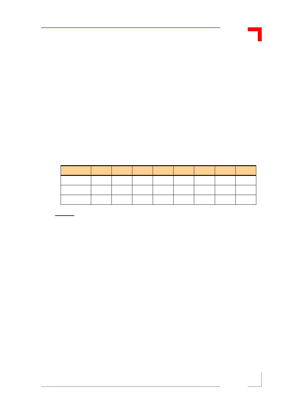
Table 4-1: Registers DOUT00 to DOUT07
MSB
Bit 6
Bit 5
Bit 4
Bit 3
Bit 2
Bit 1
LSB
Read
IE
0
0
0
STH
STL
DOH
DOL
Write
IE
—
—
—
—
—
DOH
DOL
Reset
0
0
0
0
0
0
0
0