Pb-dout8, Installation – Kontron PB-DOUT8 User Manual
Page 27
PB-DOUT8
22 Oct 98
Installation
Page 3 - 5
Man. ID 17984, Rev. Index 0110
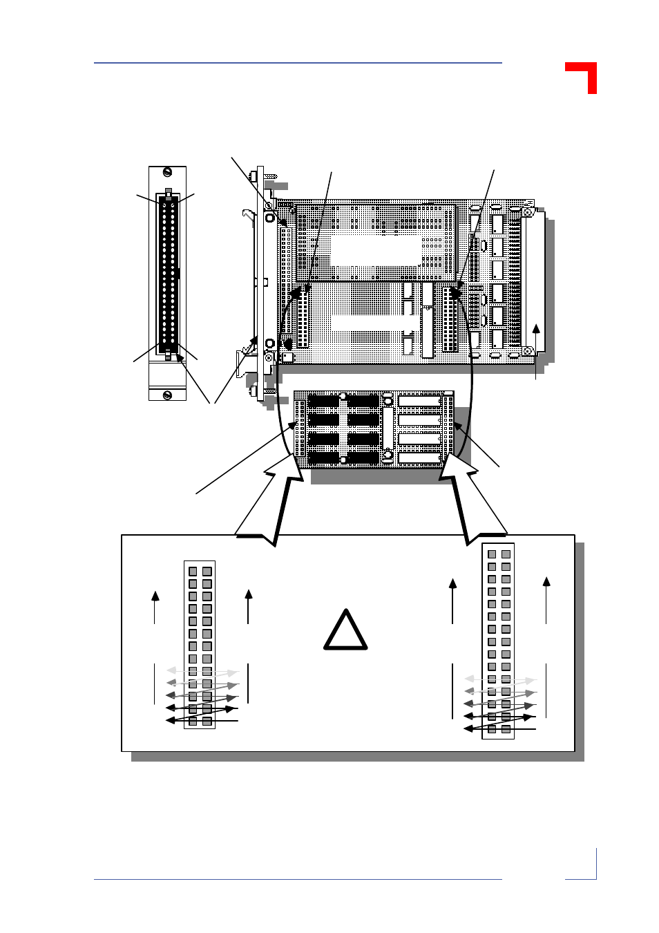
Figure 3-3: PB-DOUT8 Carrierboard Connection
PB-REL
(ready for fitting)
PB's ST2
Short
Connector
(26-Way)
PB's ST1
Long
Connector
(30-Way)
VMOD-2's ST3
Front Panel
Connector
(50-Way )
VMOD's ST1
VMEbus
Connector
(96-Way )
VMOD-2's ST2 (on-board)
50-way Header
Position B
Position A
Fitted PB-REL
VMOD
2
Pin 4 9
Odd
pins
Pin 1
Pin 5 0
Eve n
pins
Pin 2
PB's ST2 and ST1
pin distribution as
seen from the PB's
component side.
25
Odd
Pins
1
26
Even
Pins
2
VMOD-2's two 26-way
Headers BU2a (upper)
BU2b (lower)
VMOD-2's tw o 30/45-way
Header BU1/0a (upper PB)
BU1/0b (lower PB location)
29
Odd
Pins
1
30
Even
Pins
2
Remember the PB's
ST2 pin numbers
have nothing to do
with the VMOD-2
ST2's (user I/O) pins.
!
PB-DOUT8
(ready for fitting)
PB-DOUT8
(ready for fitting)
- CP3003-SA uEFI BIOS (72 pages)
- CP3003-SA (36 pages)
- CP3002 (38 pages)
- CP3002-RC uEFI (64 pages)
- CP-RIO3-05 (42 pages)
- CP3002-RC (30 pages)
- CP342 (52 pages)
- CP930 (46 pages)
- CP932 (52 pages)
- CP346 (72 pages)
- CP384 (66 pages)
- CP383 (74 pages)
- CP382 (58 pages)
- CP381 (60 pages)
- CP372 (64 pages)
- CP371 (60 pages)
- CP-RIO3-04S (38 pages)
- CP390 (36 pages)
- CPS3410 (9 pages)
- CPS3402 (9 pages)
- CPS3105 (9 pages)
- CPS3101 (9 pages)
- CPS3003-SA (19 pages)
- PB-SIO4 (34 pages)
- PB-SIO4A (34 pages)
- VMOD-2 (82 pages)
- VSBC-32 (110 pages)
- VM42 (62 pages)
- Bootstrap Loader (24 pages)
- VMP1 with Netbootloader (120 pages)
- VMP1 (106 pages)
- NetBootLoader (86 pages)
- VMP2 (142 pages)
- VMP3 (154 pages)
- CP-RIO6-923 (32 pages)
- CP-RIO6-923-F (32 pages)
- CP-RIO6-001 (28 pages)
- CP-RIO6-001-HD-VGA (46 pages)
- CP-RIO6-M (20 pages)
- CP-RIO6-B (28 pages)
- CP6925 (42 pages)
- CP6002 uEFI BIOS (76 pages)
- CP6002 IPMI (40 pages)
- CP6002 (42 pages)