Pb-dout8, Configuration, 1 pinout – Kontron PB-DOUT8 User Manual
Page 19
PB-DOUT8
22 Oct 98
Configuration
Page 2 - 3
Man. ID 17984, Rev. Index 0110
2. Configuration
2.1 Pinout
The PBDOUT-8 is connected via its carrier board to a 50-way flat-band cable or DSUB
connector. Depending on the carrier board location where the piggyback is installed (“A”
of “B”), either the upper half or the lower half of the connector pins are used
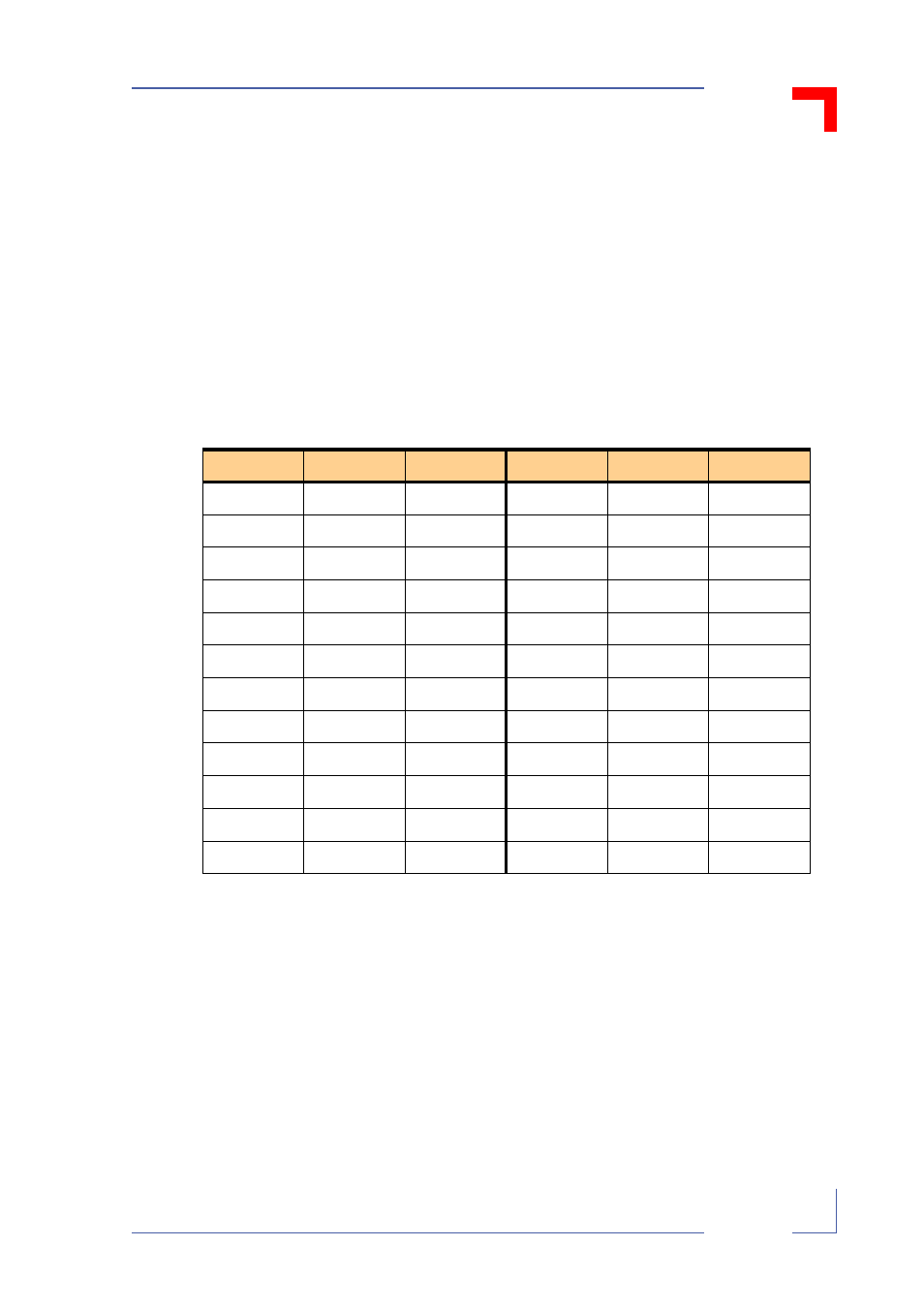
The following tables show the output registers and the corresponding output lines for the
upper (“A”) and lower (“B”) location, with reference to the relative DSUB/FB connectors
of the carrier board:
Table 2-1: PB-DOUT8 Pinout (Lower Position)
Pin
DSUB 50
FB 50
Pin
DSUB 50
FB 50
OUT07L
Pin 1
Pin 1
OUT03L
Pin 5
Pin 13
OUT07H
Pin 34
Pin 2
OUT03H
Pin 38
Pin 14
OUT06L
Pin 18
Pin 2
OUT02L
Pin 22
Pin 15
OUT06H
Pin 2
Pin 4
OUT02H
Pin 6
Pin 16
GND0607
Pin 35
Pin 5
GND0203
Pin 39
Pin 17
VSS0607
Pin 19
Pin 6
VSS0203
Pin 23
Pin 18
OUT05L
Pin 3
Pin 7
OUT01L
Pin 7
Pin 19
OUT05H
Pin 36
Pin 8
OUT01H
Pin 40
Pin 20
OUT04L
Pin 20
Pin 9
OUT00L
Pin 24
Pin 21
OUT04H
Pin 4
Pin 10
OUT00H
Pin 8
Pin 22
GND0405
Pin 37
Pin 11
GND0001
Pin 41
Pin 23
VSS0405
Pin 21
Pin 12
VSS0001
Pin 25
Pin 24