Pb-dout8, Installation, 1 carrier board interfacing – Kontron PB-DOUT8 User Manual
Page 25
PB-DOUT8
22 Oct 98
Installation
Page 3 - 3
Man. ID 17984, Rev. Index 0110
3. Installation
3.1 Carrier Board Interfacing
This section shows how to proceed with the installation of the PB-DOUT8 piggyback
module on a carrier board. Figure 2-2 shows an example configuration where two piggy-
backs standing in this case for two PB-DOUT8 modules are fit to a VMOD-2. The first
PB-DOUT8 on a carrier board would fit in the upper position (“A”), the second in the
lower position (“B”).
At first the two header-type connectors (BU1a/BU1b and BU0a/BU0b) of the carrier
board are illustrated, which directly interface to the PB-DOUT8 ST1 pin rows. The lower
case letters in the socket numbers refer to which piggyback location the connector is
used for, e.g. BU1a is socket 1 for PB-DOUT8 location “A”. An illustration showing in
detail all carrier board connectors concerning piggyback installation is given below.
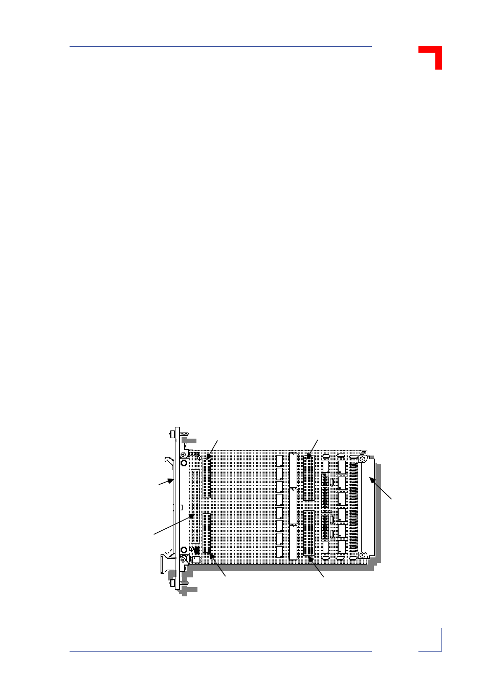
Figure 3-1: Carrier Board Connector Denominations
$
$
Important!
Please take care to note that the denominations “ST1” and “ST2”
used for the PB-DOUT8 refer only to the piggyback pin row connec-
tors themselves and fit to headers BU1a and BU2a or, respectively,
BU1b and BU2b on the carrier board.
Also the carrier boards have plugs called “ST1” (VMEbusVMEbus
connector) and “ST2” (50-way header), which have no direct rela-
tionship to those of the PB-DOUT8 connectors described in this
manual.
BU2a 26-way, 2-row
piggyback socket for
upper piggyback
BU1a/BU0a 30/45-way
2/3-row upper
piggyback s ocket
ST3 front panel
connector (50-way)
— or —
ST2 on-board
50-way header
ST1 VMOD-2's
VMEbus 96-way
connector (P1, J1)
BU2b 26-way, 2-row
piggyback socket for
lower piggyback
BU1b/BU0b 30/45-way
2/3-row lower
piggyback s ocket