Connessioni connections – FBT MXA 3240 User Manual
Page 9
I
UK
La selezione della modalità è ottenuta tramite i relativi deviatori a
tre posizioni posti a lato delle prese:
• in posizione
MIC, si seleziona la sensibilità microfonica con
alimentazione phantom disattivata;
• in posizione
pH, si seleziona la sensibilità microfonica attivando
l’alimentazione phantom (per microfoni elettrete 12/24V);
• in posizione
LINE, si seleziona la sensibilità di linea.
I collegamenti a queste prese sono riportati nella Fig. 4.2.1. Ogni
ingresso dispone di un proprio controllo di livello (
3) per dosare
opportunamente l’ampiezza dei vari segnali.
CONNESSIONI
CONNECTIONS
4.5 FILTRO pAROLA
Agli ingressi
MIC.1-2-3, MIC/LINE 4-5 è possibile inserire un filtro
parola. Per effettuare queste modifiche è necessario togliere il
coperchio dell’apparecchio:
questa operazione deve essere svolta
ESCLUSIVAMENTE da personale specializzato. L’impostazione di
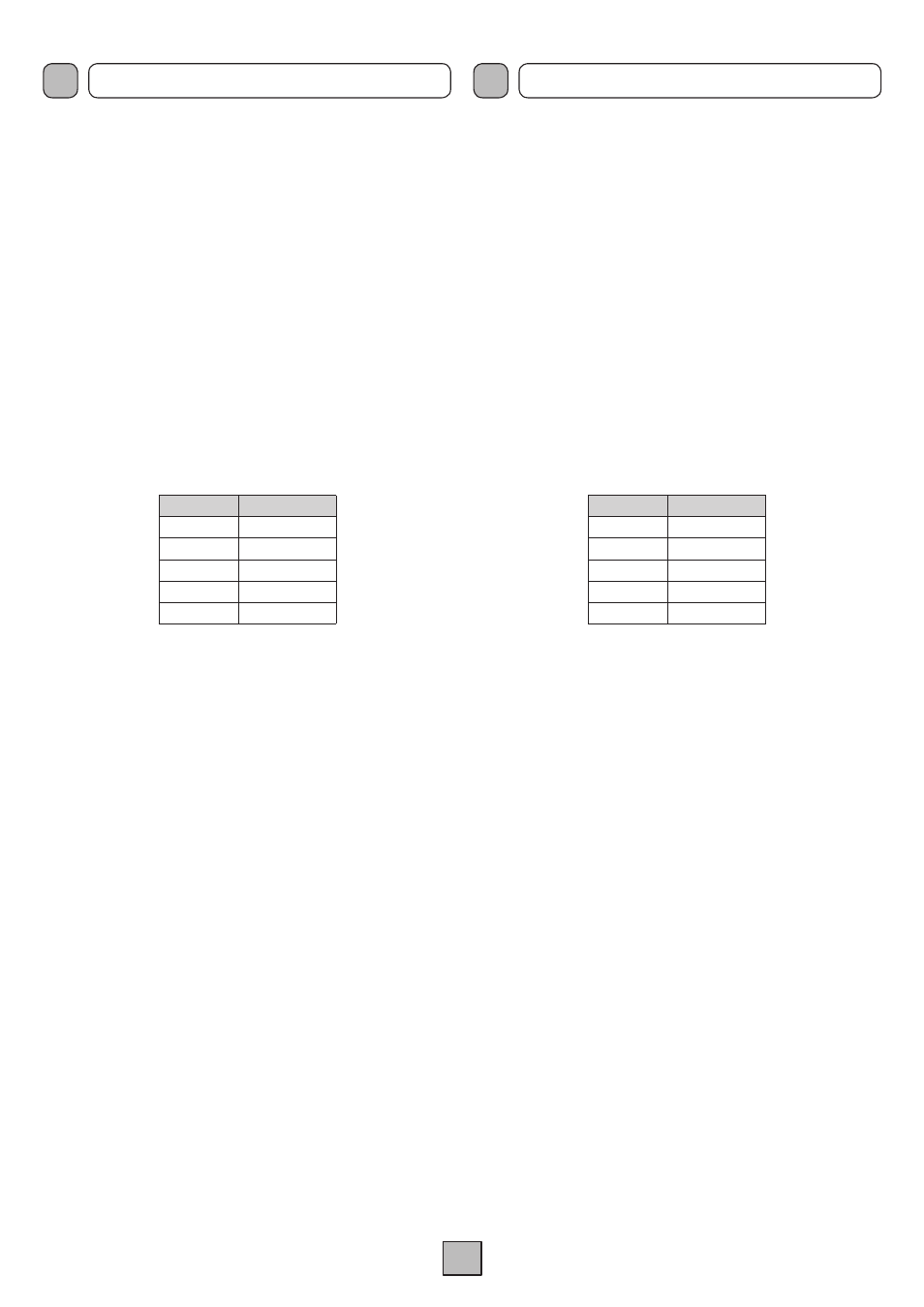
fabbrica prevede che il filtro sia disinserito: per inserirlo, posizionare
il jumper relativo all’ingresso/i interessato/i in posizione
ON,
seguendo la tabella sottostante:
Jumper
Ingresso
JP301
MIC.1
JP302
MIC.2
JP303
MIC.3/UNITS
JP304
MIC./LINE 4
JP305
MIC./LINE 5
4.6 INGRESSI AUSILIARI
Alle prese phono
TApE e CD (20) è possibile collegare 2 sorgenti
musicali ad alto livello (lettore di compact disc, riproduttore a nastro).
La doppia presa consente un veloce collegamento della sorgente
all’amplificatore tramite cavetto stereo: la miscelazione dei due
canali destro e sinistro (L/R) è realizzata internamente.
La selezione e la regolazione di livello della sorgente avviene
tramite l’apposito controllo
pROGRAM (4) posto sul pannello
frontale dell’apparecchio. La sorgente selezionata è soggetta
all’ammutolimento sia per precedenza automatica (VOX) degli
ingressi
TEL./EMERG. e MIC.1 che per la chiusura del contatto
pR (precedenza) o in caso di chiamata proveniente da postazioni
microfoniche
MbT 1106.
4.7 INGRESSO TELEFONICO
L’apparecchio è predisposto per il collegamento ad un sistema
telefonico tramite la morsettiera
TEL./EMERG. (26). Tale ingresso
è bilanciato a trasformatore, possiede un proprio controllo di livello -
LEV. (27) - ed è dotato di circuito VOX per la diffusione dei messaggi
con priorità più elevata rispetto a qualsiasi altro ingresso, eccetto le
postazioni
MbT 1106 conformemente alle impostazioni di priorità
selezionate.
4.8 USCITA “MUSIC ON HOLD”
A questi morsetti (
25) è disponibile il segnale della sola sorgente
selezionata sugli ingressi ausiliari (
20); tale segnale non è soggetto
all’azione di precedenza microfonica o telefonica. In particolare,
l’uscita bilanciata a trasformatore (morsetti COM-HOT di fig. 4.8.1)
può essere utilizzata per il pilotaggio di un ulteriore amplificatore, di
un centralino telefonico od altro. L’uscita di potenza (morsetti MON-
GND) è in grado di pilotare direttamente un piccolo altoparlante
monitor da 8 ohm con potenza massima di 1 W.
The operating mode can be selected by means of the specific three-
position switches next to the sockets:
• in the
MIC position the sensitivity of the microphone with the
phantom power supply de-activated is selected;
• in the
pH position the sensitivity of the microphone with
the phantom power supply activated (for 12/24V electret
microphones) is selected;
• in the
LINE position the sensitivity of the line is selected.
The connections to these sockets are shown in Figure 4.2.1. Each
input has its own level control (
3) so as to be able to adjust the
amplitude of the various different signals suitably.
4.5 SpEECH FILTER
It is possible to install a speech filter on inputs
MIC.1-2-3 and
MIC/LINE 4-5. To make these changes, the lid of the equipment
must be removed.
This operation must be carried out by
specialised personnel ONLy. According to the factory setting,
the filter is de-activated. To activate it, place the jumper referred
to the input in question in the
ON position, in accordance with the
following table:
Jumper
Input
JP301
MIC.1
JP302
MIC.2
JP303
MIC.3/UNITS
JP304
MIC./LINE 4
JP305
MIC./LINE 5
4.6 AUXILIARy INpUTS
It is possible to connect two high-level sources of music (CD player,
tape recorder) to the
TApE and CD (20) phono sockets. Thanks to
the fact that there are two sockets, it is easy to connect the source
rapidly to the amplifier by means of a stereo cable: mixing of the two
channels (left and right - L/R) is carried out internally. The source is
selected by means of the selector
pROGRAM (4) provided for this
purpose on the front panel of the equipment. The source selected
is subject to muting both due to automatic precedence (VOX) of
the
TEL./EMERG. and MIC.1 inputs and following closure of the
pR (precedence) contact, or in case of a call from a MbT 1106
microphone station.
4.7 TELEpHONE INpUT
The equipment has provisions for connection to a telephone system
via the
TEL./EMERG. terminal strip (26). This input is balanced by a
transformer, has its own level control -
LEV. (27) – and is equipped
with a VOX circuit for broadcasting messages with a higher priority
than any other input except for the
MbT 1106stations, in accordance
with the priority settings that have been selected.
4.8 “MUSIC ON HOLD” OUTpUT
The signal of the only source selected on the auxiliary inputs (
20)
is available on these terminals (
25). This signal is not affected
by the use of telephone precedence. In particular, the balanced
transformer output (strips COM-HOT, Fig. 4.8.1) can be used to drive
an additional amplifier, a telephone exchange or other equipment.
The power output (terminals MON-GND) is capable of driving
directly a small 8 ohm monitoring loudspeaker with a maximum
output of 1 W.