ETS-Lindgren 2005 Single Axis Positioner User Manual
Page 20
20 |
Assembly and Installation
3.
Position the AP so that the connections on the turntable are easily
accessible and located closest to available feed through panels and
power supply connections. Verify that the supplied serial cable, as well
as any user supplied RF cable(s), is long enough to reach from the AP
unit to the feed through panel that will include the RS232 filter before
settling on an orientation.
4.
Ensure than any power supply feed or other conduits or connector
panels installed on the floor near the AP are located outside the
perimeter of the AP motor base. When working around the table, avoid
stepping on any cables or their connectors. The cables will be installed
in a later step.
5.
Use a marker, with the AP in the desired position, to mark around the
perimeter of the table base. These marks will be used for reference if
the assembly moves.
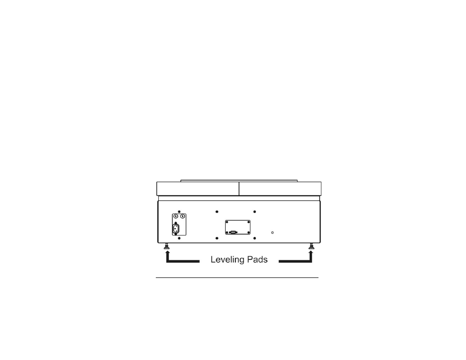
6.
Once the position of the AP has been determined, the table must be
leveled. Using a leveling instrument (torpedo laser level or some other
device) level the AP by turning the level mount pads on the bottom of
the motor base. When the turntable is level, tighten all lock nuts on the
leveling pads to lock the height of the AP into place.
Absorber and Support Column Installation
7.
Prior to installing the support column, insert the three one-inch
diameter mounting pegs into the spaces on top of the motor base.
8.
Next, place the center circular absorber piece over the support pegs.