Vi: vertical splice joints, Vertical splice joints – EFCO S5900 Inside Glazed User Manual
Page 9
EFCO CORPORATION 6/2012 PART NO. Y352
Page 9 of 18
Series 5900 Inside Glazed Curtain Wall Installation Instructions
2 1/2
"
PRESSURE
PLATE SCREWS
SEALANT AT
MULL JOINT
CO
VE
R D
IM
E
N
S
IO
N
COVER DIM
E
NSION
PR
ESSU
RE
B
AR
DIM
.
PRE
S
S
UR
E BA
R
DI
M.
MULL
DIM.
MULL DI
M.
3 1/
2"
MA
X.
2"
1/
2"
E
X
P
.
JT.
4"
RE
F.
1/
2
"
1/
2"
JT.
1"
4 1/
2" SP
LI
CE
2"
2"
1"
1" MIN.
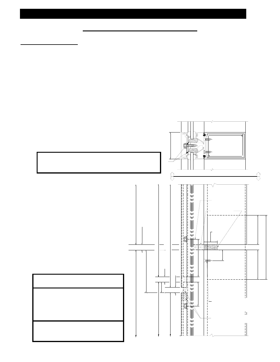
Backer rod & sealant at
top of lower cover
VI: Vertical Splice Joints
Vertical Splice Joints
A.)
Space vertical mullion expansion joints per “APPROVED” shop drawings.
B.)
Keep in mind that spacing may vary with job site temperature. On multiple stacked
applications, key horizontals must be installed to establish grades regardless of
expansion joint dimension.
C.)
Splice joints should occur at spandrel areas.
D.)
Mullion splice joints for this system are not designed to compensate for varying floor
levels. (Reference “APPROVED” shop drawings for allowable adjustment, i.e.,
anchors.)
E.)
The splice joint width should be based on
sealant movement capabilities and the
following formula.
F.)
Where head clearance is
insufficient to allow top
mullions to be lifted over the
splice sleeve, a retractable
sleeve will be used. The
sleeve is taped in the top
mullion and dropped to the
stop screw in the mullion
below.
G.)
Do not match drill anchors
until a check of expansion
joints and wall installation is
performed.
Linear expansion for aluminum in inches =
Length X F (temperature degrees difference in
Fahrenheit) X .0000129.
Note: All anchors must be fixed
before glazing begins.
Note: When the mullion splice is
shop installed in the lower
mullion, screws will be used
in the standard location as
shown.
Erector Note: Apply no screws
below splice in the upper pressure
plate.
Attach splice sleeve to
lower mullion with (2)
#10-12 X ¾” PLFHSMS.