EFCO S5500 SSG User Manual
Page 25
EFCO CORPORATION 6/2012
PART NO. Y554
Series 5500 Silicone Structural Glazed Curtain Wall Installation Instructions
Section III: Typical Anchorage Methods
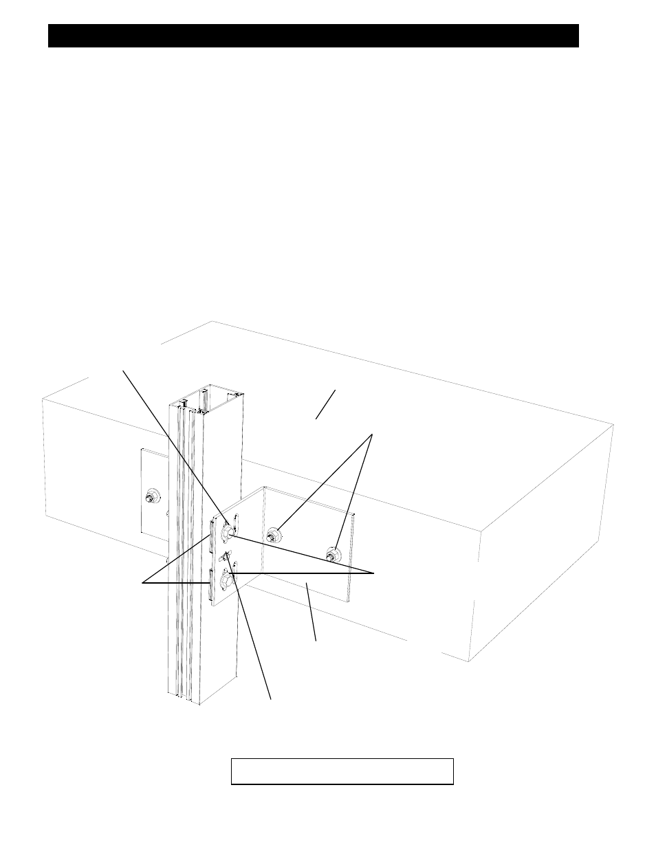
STEP #7 INSTALL FRAME COMPONENTS – WELDED WIND LOAD ANCHORS
For installations with multi-spans, follow applicable notes from Step 8. Match drill the mullion
through the
CENTER
of the set of slots in the anchor.
NOTE: The holes must be a minimum of 1” from the back of the mullion in order to clear any steel
reinforcement located inside the system as may be required on a job specific basis.
Use a bolt with a flat washer at the bolt head end. At the nut end of the bolt, use a flat washer,
then a spring lock washer next to the nut as shown. Shim each bolt as shown.
Important:
The nut must be tightened sufficiently to completely compress the spring lock washer.
Back the nut off a quarter to half turn to allow free movement of the connection.
The threads of the bolts must be staked, or Loctite must be used to prevent the nut from loosening
from the bolt. Remove the temporary alignment screws. Refer to the approved shop drawings for
anchor locations, bolt sizes, welding requirements, and other job specific information.
BUILDING
STRUCTURE
STEEL ANCHOR PER
SHOP DRAWINGS
Bolt anchor to building
structure per approved
shop drawings.
Match drill through
center
of slots.
TEMPORARY ALIGNMENT SCREW (#12 X
1” TEK SCREW) Note: Screw
must
be re-
moved from wind load anchor after bolt
installation to allow free movement.
HIGH IMPACT
POLYSTYRENE
HORSESHOE SHIMS
AT EACH BOLT
Match drill through
center
of slots.
BOLTED WIND LOAD ANCHORS