Dynojet 250: Torque Module User Manual
Page 22
Torque Module Installation and User Guide for Model 250 Dynamometers
C H A P T E R 2
Torque Cell Calibration
2-6
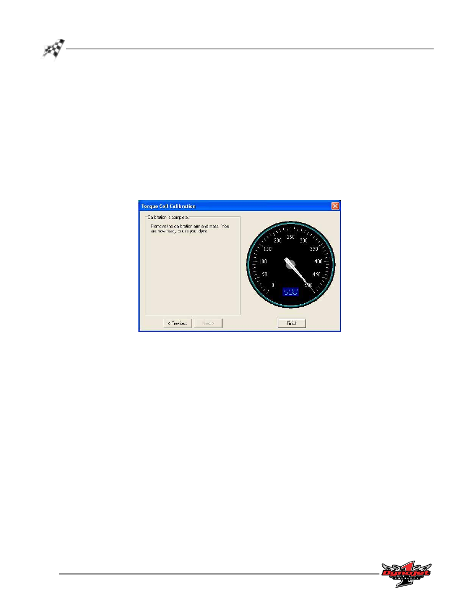
While installing the calibration weights, you should notice the Torque Gauge on the
DynoTrac Window moving from 0 to about 500 foot-pounds.
Note: The Torque Gauge may or may not be in this range. If the torque cell has
been previously calibrated incorrectly or has not been calibrated for a while, the
gauge may show values out of this range until calibration is complete.
Note: Let the torque gauge needle stabilize before clicking Next.
9
From the Span Calibration window (Figure 2-4), click Next to continue.
Note: At this point, the value on the gauge should match the value on the
calibration arm.
10 Remove the calibration arm and weights and click Finish.
Figure 2-6: Calibration Is Complete Window
- 150: Kart and ATV Dynamometers (44 pages)
- 150: Dyno Drum Cover for Kart and ATV Dyno Motorcycle Option (3 pages)
- 150: WinPEP 7 (170 pages)
- 168: Eddy Current Brake (27 pages)
- 200: Eddy Current Brake (45 pages)
- 200: Replacing the Starter Ring Gear (7 pages)
- 200: Safety Switch (3 pages)
- 200: DynoWare EX+ Upgrade Installation Guide for Motorcycle Dynos (20 pages)
- 200: Throttle Stop (3 pages)
- 200: Eddy Current Brake Driveline Upgrade (17 pages)
- 200i: High Pressure Blower (20 pages)
- 200: Installation Guide (73 pages)
- 200i: Pit Installation Guide (154 pages)
- 200i: Pre-Installation Guide (52 pages)
- 200i: Installation Guide (184 pages)
- 200i: Air Brake and EEC Kit (40 pages)
- 200i: Dynamometer Wiring Schematic (2 pages)
- 200i: Folding Ramp (15 pages)
- 200i: Control Panel Interface Upgrade (S/N 201xxxx) (31 pages)
- 200i: Control Panel Interface Upgrade (S/N 202xxxx) (29 pages)
- 200i: Motorcycle Exhaust Extraction System Drawings (18 pages)
- 200iP: Pit Installation Guide (148 pages)
- 200iPX: Installation Guide (163 pages)
- 200iPX: Installation Guide (52 pages)
- 200ix: Pit Installation Guide (163 pages)
- 200ix: Extended Carriage and Trike Adapter Assembly (15 pages)
- 200iX: Upgrade Installation Guide (56 pages)
- 200ix: Extended Carriage with Trike Adapter Assembly (13 pages)
- 224: CE Package (17 pages)
- 224: Maintenance Guide (35 pages)
- 224: Installation Guide (78 pages)
- 224/4WD: Installation Guide (77 pages)
- 224: Pit Installation Guide (56 pages)
- 224x: Above Ground Four Post Lift Dimensions (1 page)
- 224x: Pre-Installation Guide (63 pages)
- 224x: 4WD Dyno Air and Wiring Schematic (2 pages)
- 224: Eddy Current Brake (73 pages)
- 224: Pit Eddy Current Brake (69 pages)
- 224xLC2: Quickstart guide for DWRT (2 pages)
- 248: Pit Installation Guide (74 pages)
- 248: Installation Guide (58 pages)
- 248: DynoTRAC User Guide with Variable Brake (14 pages)
- 248: DynoWare EX+ Upgrade (22 pages)
- 248: Optical RPM Sensor (22 pages)
- 248: Proportional Air Brake (21 pages)