Bottom view (wiring label), Warning, Special wiring instructions – Code 3 TriCore NarrowStik Controller User Manual
Page 6: Front facing wiring of the narrowstik
6
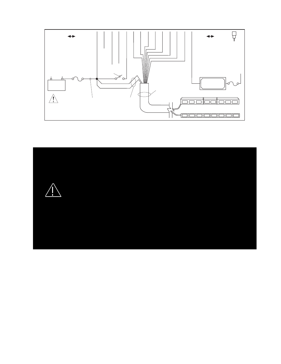
Figure 3- Rear panel connections and wiring label located on
bottom of the control head.
Bottom View (wiring label)
Larger wires and tight connections will provide longer service life for components. For high current wires it
is highly recommended that terminal blocks or soldered connections be used with shrink tubing to protect
the connections. Do not use insulation displacement connectors (e.g. 3M
®
Scotchlock type connectors).
Route wiring using grommets and sealant when passing through compartment walls. Minimize the number
of splices to reduce voltage drop. High ambient temperatures (e.g. underhood) will significantly reduce the
current carrying capacity of wires, fuses, and circuit breakers. Use "SXL" type wire in engine compartment.
All wiring should conform to the minimum wire size and other recommendations of the manufacturer and
be protected from moving parts and hot surfaces. Looms, grommets, cable ties, and similar installation
hardware should be used to anchor and protect all wiring. Fuses or circuit breakers should be located
as close to the power takeoff points as possible and properly sized to protect the wiring and devices.
Particular attention should be paid to the location and method of making electrical connections and splices
to protect these points from corrosion and loss of conductivity. Ground terminations should only be made
to substantial chassis components, preferably directly to the vehicle battery. The user should install a
fuse sized to approximately 125% of the maximum Amp capacity in the supply line to protect against
short circuits. For example, a 30 Amp fuse should carry a maximum of 24 Amps. DO NOT USE 1/4"
DIAMETER GLASS FUSES AS THEY ARE NOT SUITABLE FOR CONTINUOUS DUTY IN SIZES ABOVE
15 AMPS. Circuit breakers are very sensitive to high temperatures and will "false trip" when mounted in hot
environments or operated close to their capacity.
wARNING!
Narrowstik™ / wingMan™ / LC-Stik / Large LED Narrowstik™ / Lightbar wire Designations
The manual for the Narrowstik (and other LED models) contains detailed information related to wiring and mounting of the Narrowstik
itself. Refer to figure 4, on page 7, for additional information on the function of each wire in the 10-wire and 11-wire cable and Nar-
rowstik.
Special wiring Instructions
Front facing wiring of the Narrowstik™
The standard wiring method is for a rear-facing, driver side cable exit system as shown in figure 4. If it is desired to mount the device
as a front-facing, or passenger side cable exit, system the LED control wires will have to be reversed as indicated. The connector
shown in figure 4 DOES NOT have the wires reversed. The connector shown has standard rear facing cable exit wiring.
Wiring for Narrowstik Models with outboard flashing modules:
If you want the modules in the outboard positions to alternate during any arrow pattern (LFT, CTR, RHT), set the End Flash slide
switch to the ENABLE position and program the unit for 5 or 6 head arrow patterns. There are no changes to how the NarrowStik is
wired to the control head.
P/N - T11709
REV. 0
ARTBOARD - XA11709
LED NARROWSTIK CONTROL HEAD (BOTTOM)
11/11/09
10 WIRE CABLE
LIGHT BAR
NARROWSTIK
CNTL
HEAD PWR
PROGRAM
(+12V SW) BACKLIGHT
(DIM) WHITE
EXTERNAL
FLASH
BROWN
ORANGE
VIOLET
TAN
GREEN
GRA
Y
YELLOW
BLUE
AUX. OUTPUT
(SUPPLIES GROUND)
+12V
- SEE INSTRUCTIONS FOR FURTHER INFORMATION.
- DO NOT SHORT OUTPUTS TO +12 V.
- DISCONNECT POWER BEFORE SERVICE.
16 GA. WIRE
MINIMUM
15 AMP FUSE
OR CIRCUIT
BREAKER
(user supplied)
REAR VIEW
- LED USE ONLY.
PROGRAMMING:
1. APPLY POWER TO CONTROL
HEAD.
2. PLACE SLIDE SWITCH INTO
DESIRED FUNCTION.
3. TOUCH PROGRAM INPUT TO
GROUND MOMENTARILY AND
RELEASE. REPEAT UNTIL
DESIRED PATTERN IS SELECTED.
4. PROCEED TO NEXT FUNCTION IF
DESIRED.
TO RESTORE FACTORY DEFAULT,
HOLD PROGRAM INPUT TO
GROUND FOR 5 SECONDS.
RED/WHITE
RED
USER SUPPLIED
SWITCH
BLU
YEL
GRY
GRN
TAN
VIO
ORG
BRN
LIGHT HEAD
POWER
BLU
YEL
GRY
GRN
TAN
VIO
ORG BRN
T11709
3A
MAX.
3A FUSE
GND
GROUND
16 GA. MIN.
CONNECT
TO BATTERY
NEGATIVE (-)
(SEE MANUAL
FOR DET
AILS)
WARNING
END FLASH
ENABLE
DISABLE
DIM CONTROL
STEADY
PWM
AUXILIARY
DEVICE
3A MAX.
NEG. POS.
BATTERY