Rear panel connections – Code 3 TriCore NarrowStik Controller User Manual
Page 4
4
POwER
The POWER button turns the control head ON/OFF and is a push-on / push-off switch. When the POWER button is activated the
control head will perform the currently selected traffic directing or warning pattern. The control head can be operated with the POWER
switch in the OFF position by use of the External Flash input. See the External Flash Input section for details.
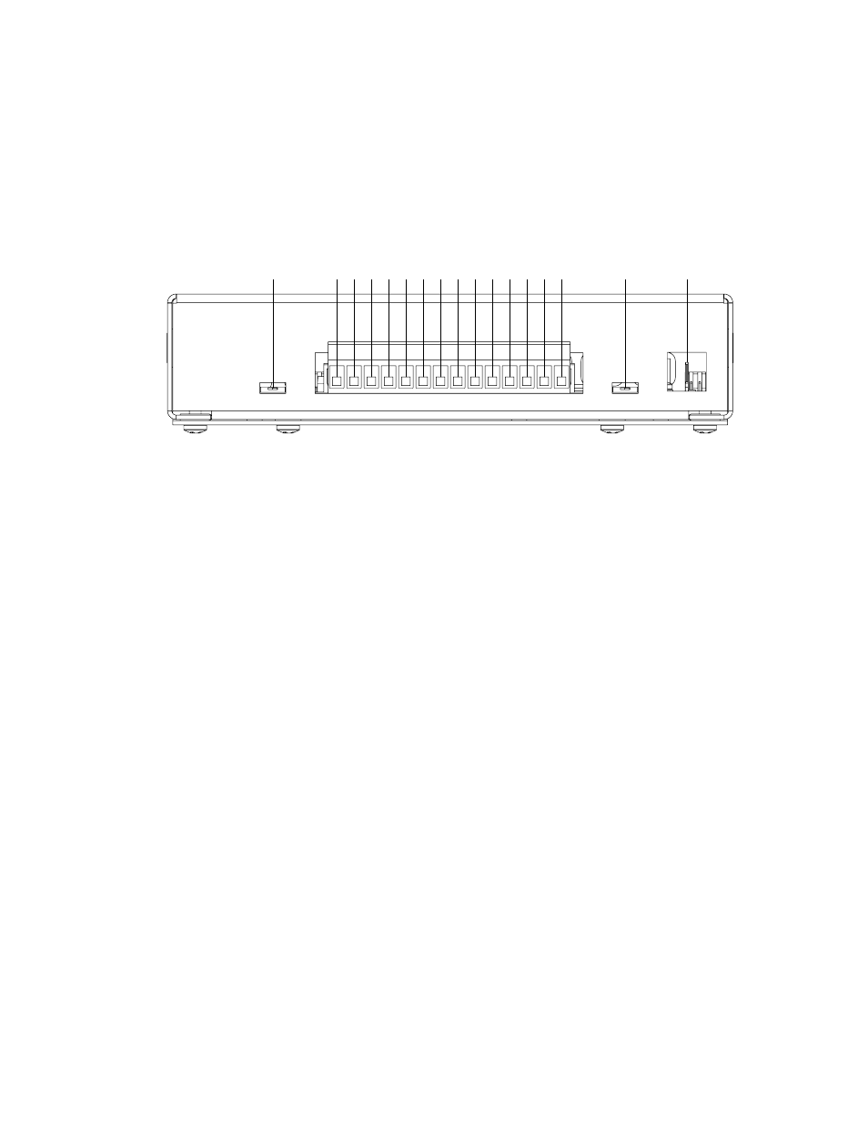
Figure 2 - Rear Panel View
REAR PANEL CONNECTIONS
Control Head Power Input
This input provides +12V POWER to the control head. This input will draw approximately 250 mA maximum when the control head is
active and the DIM mode is selected. This input is reverse polarity and transient protected.
Program Input
This input is used for programming the control head. With POWER on the control head, pulling this input terminal to GND momentarily
until the indicator LEDs (and Narrowstik™ if connected) go out, and then releasing, will step through the available traffic directing
signal options for the particular slide switch position currently selected. Holding this input to GND for 5 seconds or longer will reset the
control head to the factory default settings. Refer to the Programming section for further details.
Backlighting Input
This input provides power for the backlighting. It is recommended that this input be connected to an IGNITION switched source of
+12V or equivalent to prevent battery drain. This input will draw approximately 150 mA @ 12.8V.
Dimming Control Output
This output terminal provides +12V when the DIM button is activated. With the White wire from the 11-wire Narrowstik™ cable con-
nected to this terminal the Narrowstik will run in a reduced intensity (DIM) mode until the DIM switch is turned off. This output is a solid
state internally protected output and is designed to operate the Dimming feature only. This output will provide +12V in either position
of the DIM Control Slide Switch.
External Flash Control Input
This input will allow remote activation of the FLSH function when the control head POWER switch is off by applying +12V to the
designated External Flash input terminal. The active pattern will be the same as that programmed for the FLSH switch position. Turn-
ing on the control head, by pushing in the POWER button, activates the currently selected slide switch mode if other then FLSH is
selected. This input draws approximately 250 mA maximum when activated and with the DIM mode active.
DIM Control Slide Switch
This switch will enable or disable the PWM feature of this unit. When set in the PWM position, the unit will pulse the eight outputs
whenever the DIM push button on the front of the unit is on. The pulsed outputs will cause the TriCore NarrowStik to operate in a
reduced intensity (DIM) mode until the DIM switch is turned off. Only use the PWM setting of this switch with the TriCore NarrowStik.
Use the STEADY setting for all other NarrowStik Products. Improperly setting this switch will affect the performance of the warning
light system. The DIM CONTROL miniature slide switch can be accessed through an opening in the rear of the unit. To adjust this
switch use the tip of a pen or small screwdriver to gently slide the actuator to the desired position (see BOTTOM Label).
Note: The DIM CONTROL miniature slide switch has no affect on the Dimming Control Output.
End Flash Slide Switch
This switch will enable or disable the End Flash feature of this unit. When set in the End Flash position, the unit will alternate flash out-
puts 1 and 8 at a rate of 250ms each whenever LFT, CTR, or RHT is selected with the slide switch on the front of the unit. The END
FLASH miniature slide switch can be accessed through an opening in the rear of the unit. To adjust this switch use the tip of a pen or
small screwdriver to gently slide the actuator to the desired position (see BOTTOM Label).
Note: The END FLASH feature can only be enabled when the unit is programmed for 5 or 6 head arrow patterns.
+12V CONT HD PWR
PROGRAM INPUT
(+12V SW) BACKLIGHT
(DIM) WHITE
EXTERNAL FLASH
BROWN
ORANGE
TAN
VIOLET
GREEN
GRAY
YELLOW
BLUE
AUX INPUT (GND SW)
DIM CONTROL
END FLASH
CONTROL HEAD GND