Control head installation and wiring, Installation & mounting, Wiring instructions – Code 3 TriCore NarrowStik Controller User Manual
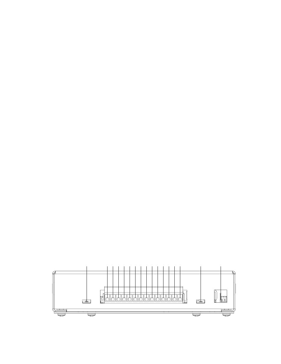
Page 5: Rear panel view
5
LED Module Control Outputs (Brown,Orange,Tan,Violet,Green,Grey,Yellow,Blue)
These eight outputs provide independent control of each LED module in the Narrowstik™. They provide a low-side (GND) signal to
each LED module. Connect the designated color from the NarrowStik cable to these terminals.
NOTE: These outputs are designed for LED modules only. DO NOT connect a halogen or incandescent Arrowstik™ to these
outputs. Damage may occur to the control outputs.
AUX Input
This input was designed to provide a low-side (GND) signal to an external LED load of up to 3A (two LED modules). This input con-
sists of a fully protected, solid-state FET, with a 3 Amp maximum current capacity. If overloaded, this input will shut down until the
overload is removed. To drive higher current loads, this input can be used to control a relay if desired by connecting the low side of the
relay coil to this terminal. Pushing in the “AUX” button located on the front panel activates the auxiliary input. The “AUX” function is in-
dependent of the state of the control head POWER switch. NOTE: The “AUX” output will operate with the control head “POwER”
button in the ON / OFF position, however, +12V must be applied to the control head Power Input terminal to operate.
Control Head Ground (GND)
The ground connection is a 1/4" PC mount male quickslide. A 1/4" fully insulated female quickslide is included in the parts bag for con-
nection to a 16 gauge wire or larger. If desired, any 1/4" female quickslide capable of a 16 gauge wire or larger can be used.
Control Head Installation and wiring
Installation & Mounting
The following procedure outlines mounting of the control head using the enclosed mounting strap and hardware.
1. Position the mounting strap in the selected location. Mark the locations for the mounting hardware ( user supplied ).
2. Drill the mounting holes in the areas marked.
3. Using the mounting hardware ( user supplied ), secure the strap to the mounting location.
4. With the bail strap in place, position the control head into the bail until the mounting holes, located in the control head cover,
align with the slots in the bail.
5. Using the washers and bolts ( supplied ), secure the control head into the bail.
Control Head wiring
The view below, shows the terminal designations for the 14-position plug located on the rear of the unit. Figure 3 on page 6 shows the
wiring label located on the bottom of the control head. Connect the wires from the NarrowStik cable and user supplied auxiliary function
wires as shown in the wiring diagram. Recommended wire size and fusing is also shown in the diagram. The control head GND will be
connected using the 1/4" quickslide included with the unit. Refer to the Operation section, page 3, for details on individual wire functions.
wiring Instructions
+12V CONT HD PWR
PROGRAM INPUT
(+12V SW) BACKLIGHT
(DIM) WHITE
EXTERNAL FLASH
BROWN
ORANGE
TAN
VIOLET
GREEN
GRAY
YELLOW
BLUE
AUX INPUT (GND SW)
DIM CONTROL
END FLASH
CONTROL HEAD GND
Rear Panel View