Front panel controls, Warning – Code 3 TriCore NarrowStik Controller User Manual
Page 3
3
Mechanical
Depth: 3 1/2 inches not including connector
Width: 6 1/2 inches
Height: 1 1/2 inches
Weight: 1.2 lbs.
Operation
The following sections explain the operation of the control buttons and slide switch as well as the function of the input and
output terminals on the 14-position plug and miniature slide switches located on the rear of the unit.
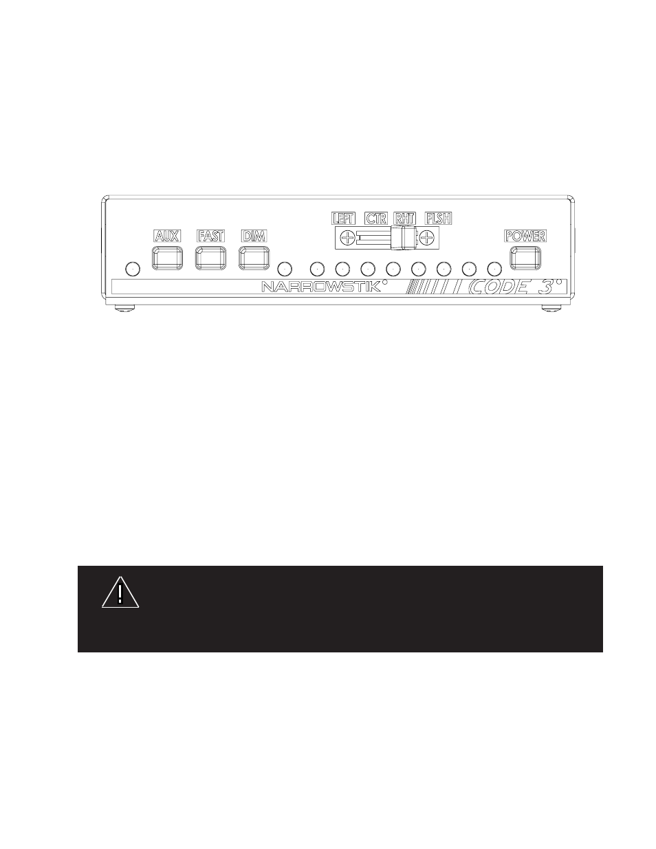
Figure 1 - Front Panel View
FRONT PANEL CONTROLS
A
R
G
A
A
A
A
A
A
A
Output Indicator LEDs
The eight front panel amber LEDs indicated with an "A" in figure 1, indicate the activity on the outputs for each selection. For example,
when in LFT mode the LEDs will cycle ON / OFF from right to left.
AUX
This auxiliary device control was designed specifically to operate customer provided LED modules or other devices not part of the
NarrowStik Product. The “AUX” function is independent of the state of the control head ON/OFF POWER button. When the auxiliary
input is active, it is indicated by the red LED marked with an "R".
FAST
With any of the directional modes selected ( LFT,CTR,RHT) pushing in the button marked FAST will cause the selected directional
mode to operate at a faster rate, with the same intensity. The Fast Mode Override has no effect when in the FLASH position.
DIM
Pushing in the button marked DIM will place +12V on the DIM output terminal and white wire, if connected, causing the Narrowstik™
to DIM. In addition, pushing the DIM button will pulse the eight outputs causing the TriCore NarrowStik to DIM. This feature is set us-
ing the miniature slide switch on the rear of the unit (See DIM Control Slide Switch on page 6). This is for use when 100% intensity is
not desired, or when reduced current draw is desired. DIM operation is indicated by the green LED marked with a "G" in figure 1.
Note: Dimming capabilities are not available with LC-Stick versions.
The Dim setting reduces the light output of emergency warning lights reducing the effectiveness of
them especially in brightly lit areas. Failure to use adequate light for the circumstances can cause
motorists to fail to see the emergency vehicle and lead to serious personal injury or death. Never
use the DIM setting in a brightly lit area. Use of the DIM setting may cause emergency lights to not
comply with applicable emergency warning light standards. Use caution when using the DIM setting to
assure that motorists can clearly see the emergency vehicle.
wARNING!
LFT, CTR, RHT
With the slide switch in any of these positions the Narrowstik™ will provide a traffic directing signal with either a right-to-left (LFT), a
Center-Out (CTR), or a left-to-right (RHT) sequence. The factory default programming is for a building signal starting with either the
left most module, the right most module or the two center modules. The control head can be reprogrammed with various traffic direct-
ing options for each switch position such as a Building with 3 Flash, Traveling Ball with 3 Flash or a Build/Collapse signal. Refer to the
Programming section for more details.
FLSH
With the slide switch in this position the Narrowstik™ will provide a traffic warning signal. The factory default pattern (Flash) alternates
the inner most modules with the outer modules. The control head can be reprogrammed with several warning patterns such as Cycle
Flash, Sweep Flash, Variable Rate Flash, or multiple rates of Picket Fence and Alternating Patterns. Refer to the programming section
for more details.