Adjusting/aiming the take down/warning lights – Code 3 SuperVisor U User Manual
Page 11
11
Hardware/Parts-Cont. Items 17 Thru 21 Not Shown in Exploded View
Reference Number
Part Description
Part Number Quantity
16 Outer Mounting Bracket-Tahoe T15547 2
17
1/4"-20 X 1/2" Long Carriage Bolt Black Zinc T15541 8
18 1/4"-20 Acorn Nut Black Zinc T15540 8
19 1/4"-20 X 3/8" Long Phillips Pan Head Screw Black Zinc T89965 8
20 1/4"Internal Tooth Lock Washer T11253 16
21 #8 X 1" Long Phillips Truss Head Sheet Metal Screw Black Oxide T15280 10
22 .625 Dia Plug Cap T04797 7
23 .500 Dia Plug Cap T00337 12
Note: Some of the above listed parts may not be available for purchase!
FIGURE
7
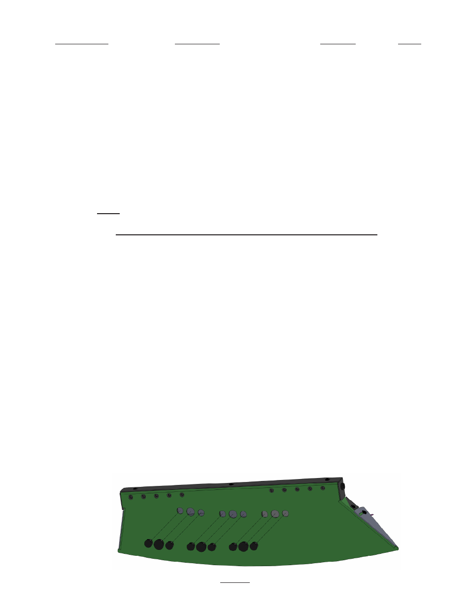
Adjusting/Aiming the Take Down/Warning Lights
1. Using a pocket knife or other thin tool, remove the (3) Take Down Light Adjustment Access Hole Caps as
shown in Figure-7 below
(Driver Side Shown---On a new install this step may not be necessary).
2. Energize the Take Down/warning Light to enable the aiming process.
3. With a phillips screwdriver (Note some versions may require a #20 Torx Driver or a 1/4" Hex Driver) loosen the
(2) Take Down Light Head Fasteners to just loosen them up, no more that 1/4 turn as shown in Figure-8 on page
12. The outer panel is shown clear to show the internal fasteners and the Take Down Light/Warning Light Head
Mounting Bracket.
4. With a 1/4" flat blade screwdriver turn the Take Down Light Head to aim it in the desired direction as shown in
Figure-9 on page 12.
5. When the Take Down Light Head is aimed in the desired direction retighten the fasteners with the phillips
screwdriver taking care not to allow the light head to move.
Note: It is advisable to hold the Take Down Light Head
in position with the flat blade screwdriver to prevent movement of the light head while tightening the fasteners. It
works best if you use a phillips screwdriver that is longer than the flat blade screwdriver as shown in Figure-10 on
page 12.
6. Replace the Take Down Adjustment Access Hole Caps and repeat Steps 1 through 6 if desired on the opposite
side of the vehicle.
Note: If extreme adjustments have been made it may be necessary to trim the cap to get it to fit
back in the hole.