Maintenance, Troubleshooting – Code 3 PSE475 Remote Strobe Power Supply User Manual
Page 11
MAINTENANCE
The PSE475 Remote Strobe Power Supply has been designed to provide trouble free service. In case of
difficulty , refer to the Troubleshooting section. Periodic inspection of power supply wiring, and strobe light
head connections for shorted or open wires will assure trouble free operation. The primary cause of short
circuits has been found to be wires passing through firewalls, roofs, etc.
Troubleshooting
NOTE: DO NOT TAMPER WITH THE POWER SUPPLY. THIS UNIT IS SOLD AS A COMPLETE MODULE,
AND IS NOT DESIGNED FOR FIELD REPAIR.
All PSE475 Remote Strobe Power Supply units are thoroughly tested before shipment. However, should you
encounter a problem during installation or during the life of the product , refer to the guide below for informa-
tion on troubleshooting. In most cases problems that occur will be related either to the power / control wiring,
or to the strobe light head cables that connect them to the strobe power supply. In the event that the strobe
power supply is at fault return the unit to the factory for service. Additional information may be obtained from
the factory technical help line at 314-426-2700 ext. 2132.
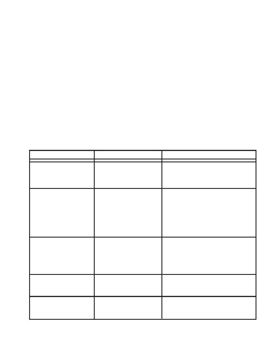
TROUBLESHOOTING GUIDE
PROBLEM
CAUSE
SOLUTION
External fuse blows
a. Power input wires reversed.
a. Check power connections.
b. Power supply failure.
b. Return for service.
c. Incorrect fuse size.
c. Replace with a 15A for +12VDC or
7.5A for +24VDC.
Light heads do not fire
a. Cable connections loose
a. Check all connections.
at power supply or light head.
b. Isolate damaged cable by disconnecting
b. Cable to light heads
one at a time. Repair or replace the
damaged and shorting to
damaged cable.
chassis.
c. Cable terminated improperly
c. Check wire orientations at 3 pin connec-
in 3 pin AMP connector.
tors.
d. Bad strobe tube.
d. Replace strobe tube assembly.
Incorrect flash pattern
a. Control harness wiring
a. Check wiring/switches. Refer to Table 1
and or switches not connected
to verify selections.
properly.
b. Light heads plugged into
b. Follow designations on label for outlets
wrong outlet on the power
and move to proper outlet.
supply.
Low strobe light intensity
a. Power supply in low power
a. Check green wire on power harness.
mode.
It should not be connected to power or
ground for HI power mode.
Flash patterns change
a. Power supply is in CYCLE
a. Brown wire is connected to +VDC. Check
continuously
FLASH mode. Proper
control harness/switches. If CYCLE MODE
operation.
is not desired change connections.
11