Code 3 MX 7000 User Manual
Page 10
Master/Slave Operation
Each 360 degree corner module consists of a "master" and a "slave" driver circuit board, 360 degree optics and LED light
engines along with a single integrated heatsink bracket.
The "master" circuit board (rear position) must always be powered for the "slave"(front position) to flash. The "master" is always
located in the rear position of the module. The lightbar is wired to allow running only the rear facing LED on each module by
removing power to the front facing "slave" module. This gives a "front-cutoff" function. The flash pattern for each corner pair
can be selected by shorting together the 2-pin header J1, on the "master" , momentarily and releasing. The module is set-up
for "Cycleflash" as a standard. Holding down the 2-pin header for 5 sec., or longer, and releasing will return the pattern to
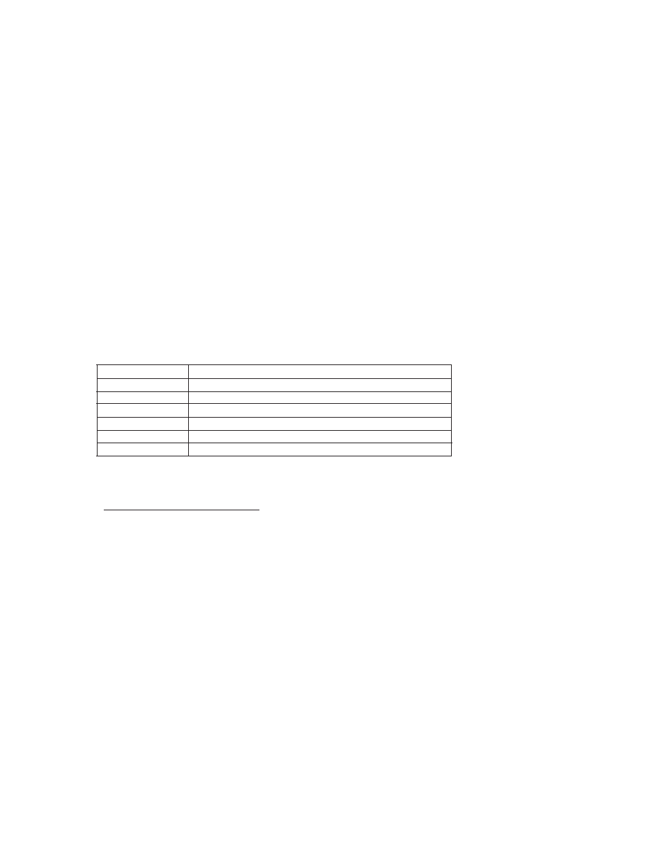
Cycleflash. The following chart describes the available patterns and order;
360 Degree Module Flash Pattern - Table 3
See Figure 22
Both heads will be in the mode selected. Both heads will flash together unless in Front Cut-off mode.
LED DIRECTIONAL MODULES
In addition to the 360 warning modules the lightbar may be equipped with a number of single head
directional warning LED modules. These modules are available in either the existing LED X™ ( 1" X 4" ) or the new Code 3®
OPTIX™ ( 1" X 6" ) and LC-LED directional modules in stationary and flashing versions ( see figure 8). The stationary versions
can be flashed by connecting the module(s) to any flasher that does not require ground through the load (example: Code 3®
700 series relay flasher). The flashing modules will have "Cycleflash" as the standard pattern. The OPTIX and LEDX flash
pattern can be changed by shorting the 2-pin header, J1 as shown in Figure 22, momentarily then releasing. Table 4 shows
the available patterns and the order when stepping through patterns. The module can be reset to "Cycleflash" by shorting the
header for greater than 5 sec. and releasing.
Operating Specifications for directional module:
Operating Voltage: 10-16 VDC, Reverse Polarity Protection
Current Draw : Flashing Module
Red/Amber - .25A avg @ 12.8 Volts
Blue/White - .4A avg @ 12.8 Volts
Steady Burn Module
Red/Amber - .5A avg @ 12.8 Volts
Blue/White - .8A avg @ 12.8 Volts
Available Colors - Red , Blue, Amber, and White
Cycle Flash
Cycles through various patterns @ 70 fpm
Five Flash
Five Pulses per flash @ 70 fpm
Quad Flash
Four Pulses per flash @ 70 fpm
NFPA
Four Pulses, 70% Duty Cycle @ 75 fpm
Triple Flash
Three Pulses per flash @ 70 fpm
Quad Pop Flash
Four Pulses per flash (3 equal, 1 extended) @ 70 fpm
Flash Pattern
Description
10