Maintenance, Specifications, Warning! dimming – Code 3 LED X NarrowStik (Large Head) User Manual
Page 10
10
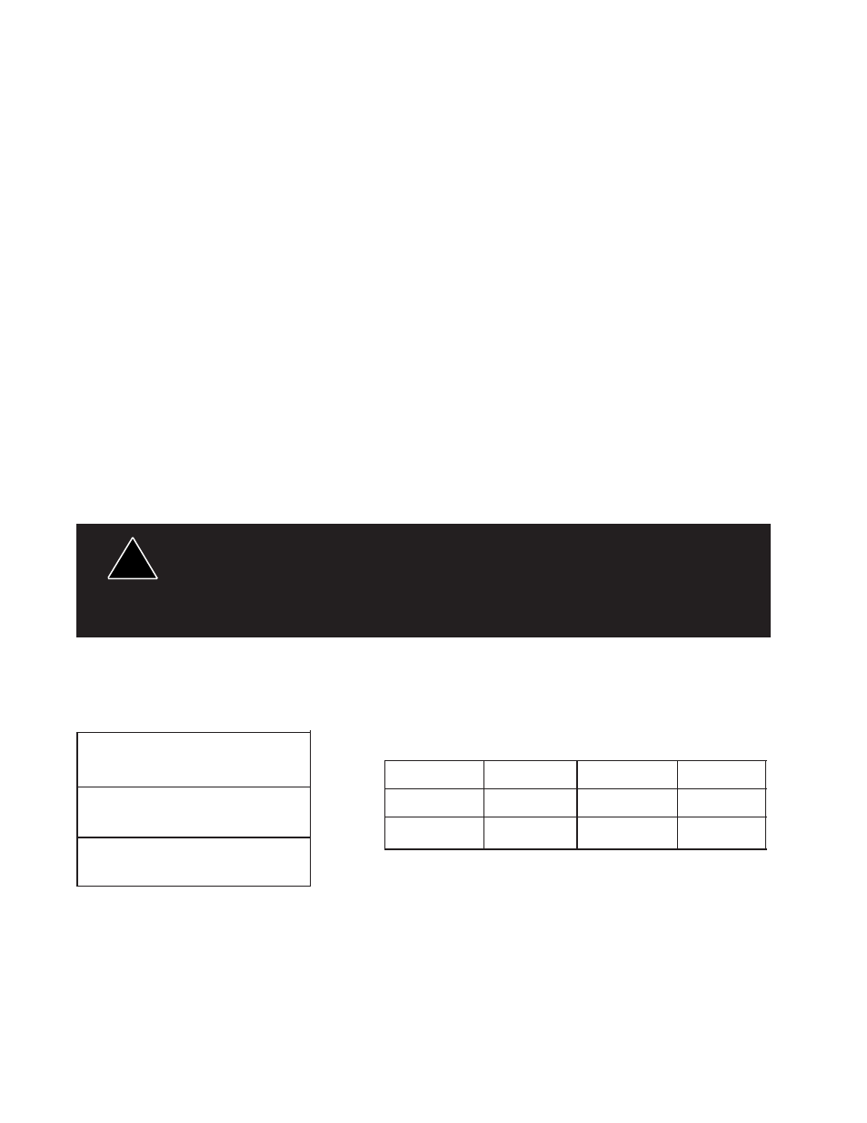
ASL-1060H Size:
60" L, 2" D, 20" H
Operating Voltage : 10 - 16VDC
Weight : 6.2 lb
Current Draw :
10 Head Split
10 Head Std
10 Head LC
ASL-SP10H Size: 33" L, 2" D, 20" H
Average :
5A
5A
1.25A
Weight : 9.8 lb
Maximum :
10A
10A
2.5A
ASLC-1060H Size: 60" L, 2" D, 20" H
Weight : 6.2 lb
Maintenance
The Large LED Narrowstik® requires minimal routine maintenance. Occasional cleaning of the lens is all that is required to sustain
maximum light output. Water or Code 3
®
lens polish and a very soft cloth is needed for cleaning. The plastic scratches easily, so cleaning
is recommended only when necessary.
Current Draw is reduced by approximately 60% in Dim mode.
The Dim setting reduces the light output of emergency warning lights reducing the effectiveness of them
especially in brightly lit areas. Failure to use adequate light for the circumstances can cause motorists to
fail to see the emergency vehicle and lead to serious personal injury or death. Never use the DIM
setting in a brightly lit area. Use of the DIM setting may cause emergency lights to not comply with
applicable emergency warning light standards. Use caution when using the DIM setting to assure that
motorists can clearly see the emergency vehicle.
!
WARNING!
Dimming
All Narrowstik models come equipped with a DIM, low power, mode as standard that allows the user to reduce the L.E.D.
intensity, if desired. The current consumption is also significantly reduced in this mode ( approximately 60% ). Dim mode
is controlled by the White wire in the 11-wire cable, see figure 5, page 5. When +12V is applied to this white wire the
modules will DIM until removed. The Narrowstik control head has an output dedicated to provide this +12V, see the
Control Head manual for details.
Note: This feature is not available on LC-Stik models.
Wiring for Narrowstik® models with outboard positions flashing:
Alternaively the Blue ( positive ) wire can be connected through a switch to +12V and the Brown ( negative ) wire can connected to
ground. When the switch is closed the Flashing modules will be enabled.
When independently flashing modules are selected to replace the standard modules in the outboard positions the BLUE and the Brown
wires will be used to activate these modules and will not be connected to the Blue / Brown outputs on the control head as usual. Instead
the Blue* ( positive) wire can be connected to +12V and the Brown* ( negative ) wire can be connected to the AUX output on the
control head. When the AUX button is activated the flashing modules will be enabled. Refer to the control head manual for further details on
use of the AUX function.
Specifications