Electrical data, Electrical data -28 – Carrier 30XW325-400 User Manual
Page 26
26
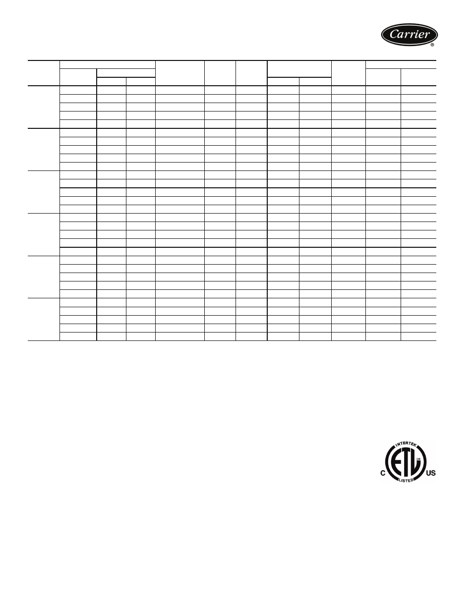
STANDARD SINGLE INPUT POWER CONFIGURATION
LEGEND
NOTES:
1. Each main power source must be supplied from a field-supplied fused
electrical service with a (factory-installed or field-installed) disconnect
located in sight from the unit.
2. Control circuit power must be supplied from a separate source through
a field-supplied disconnect. An optional control transformer may be
used to provide control circuit power from the main unit power supply.
3. Maximum instantaneous current flow (ICF) during start-up is the point
in the starting sequence where the sum of the LRA for the start-up
compressor, plus the total RLA for all running compressors is at a
maximum.
4. Maximum incoming wire size for each terminal block is 500 kcmil.
5. Maximum allowable phase imbalance is: voltage, 2%; amps, 5%.
6. Use copper conductors only.
7. The MOCP is calculated as follows:
MOCP = (2.25) (largest RLA) + the sum of the other RLAs. Size the
fuse one size down from the result. The RLAs are listed on the
nameplate.
The recommended fuse size in amps (RFA) is calculated as follows:
RFA = (1.50) (largest RLA) + the sum of the other RLAs. Size the fuse
one size up from the result. The RLAs are listed on the nameplate.
30XW
UNIT
SIZE
UNIT VOLTAGE
NO. POWER
SUPPLY
CONDUCTORS
MCA
MOCP
ICF
REC FUSE
SIZE
CONTROL CIRCUIT
V-Ph-Hz
Supplied
V-Ph-Hz
MCA and
MOCP
Min
Max
WD
XL
325
200-3-60
187
220
9
920.3
1200
1347.0
—
1200
115-1-60
20
230-3-60
207
253
9
799.0
1000
1171.1
—
1000
115-1-60
20
380-3-60
342
418
6
487.6
700
710.7
1753.7
600
115-1-60
20
460-3-60
414
506
6
401.0
500
586.2
1448.2
450
115-1-60
20
575-3-60
518
633
3
317.3
450
467.0
1157.0
400
115-1-60
20
325
HM
200-3-60
187
220
12
1168.2
1600
1848.2
—
1600
115-1-60
20
230-3-60
207
253
9
1018.4
1200
1608.6
—
1200
115-1-60
20
380-3-60
342
418
6
614.5
800
973.1
2452.1
700
115-1-60
20
460-3-60
414
506
6
510.8
700
805.0
2027.0
600
115-1-60
20
575-3-60
518
633
6
406.8
500
642.8
1620.8
450
115-1-60
20
350
200-3-60
187
220
9
920.3
1200
1347.0
—
1200
115-1-60
20
230-3-60
207
253
9
799.0
1000
1171.1
—
1000
115-1-60
20
380-3-60
342
418
6
487.6
700
710.7
1753.7
600
115-1-60
20
460-3-60
414
506
6
401.0
500
586.2
1448.2
450
115-1-60
20
575-3-60
518
633
3
317.3
450
467.0
1157.0
400
115-1-60
20
350
HM
200-3-60
187
220
12
1168.2
1600
1848.2
—
1600
115-1-60
20
230-3-60
207
253
9
1018.4
1200
1608.6
—
1200
115-1-60
20
380-3-60
342
418
6
614.5
800
973.1
2452.1
700
115-1-60
20
460-3-60
414
506
6
510.8
700
805.0
2027.0
600
115-1-60
20
575-3-60
518
633
6
406.8
500
642.8
1610.8
450
115-1-60
20
400
200-3-60
187
220
9
1041.3
1200
1400.8
—
1200
115-1-60
20
230-3-60
207
253
9
902.9
1200
1217.3
—
1200
115-1-60
20
380-3-60
342
418
6
545.2
700
736.3
1779.3
700
115-1-60
20
460-3-60
414
506
6
452.9
600
609.3
1471.3
600
115-1-60
20
575-3-60
518
633
3
366.3
500
488.8
1178.6
450
115-1-60
20
400
HM
200-3-60
187
220
12
1329.8
1600
1920.0
—
1600
115-1-60
20
230-3-60
207
253
12
1156.7
1600
1670.1
—
1600
115-1-60
20
380-3-60
342
418
6
700.9
1000
1011.5
2490.5
800
115-1-60
20
460-3-60
414
506
6
579.8
800
835.7
2057.7
700
115-1-60
20
575-3-60
518
633
6
464.4
600
668.4
1646.4
600
115-1-60
20
ICF
— Maximum Instantaneous Current Flow
HM
— Heat Machine Units
LRA
— Locked Rotor Amps
MCA
— Minimum Circuit Ampacity (for wire sizing)
MOCP — Maximum Overcurrent Protection
RLA
— Rated Load Amps
WD
— Wye-Delta Start
XL
— Across-the-Line Start
Electrical data