Typical control wiring schematics – Carrier 30XW325-400 User Manual
Page 21
21
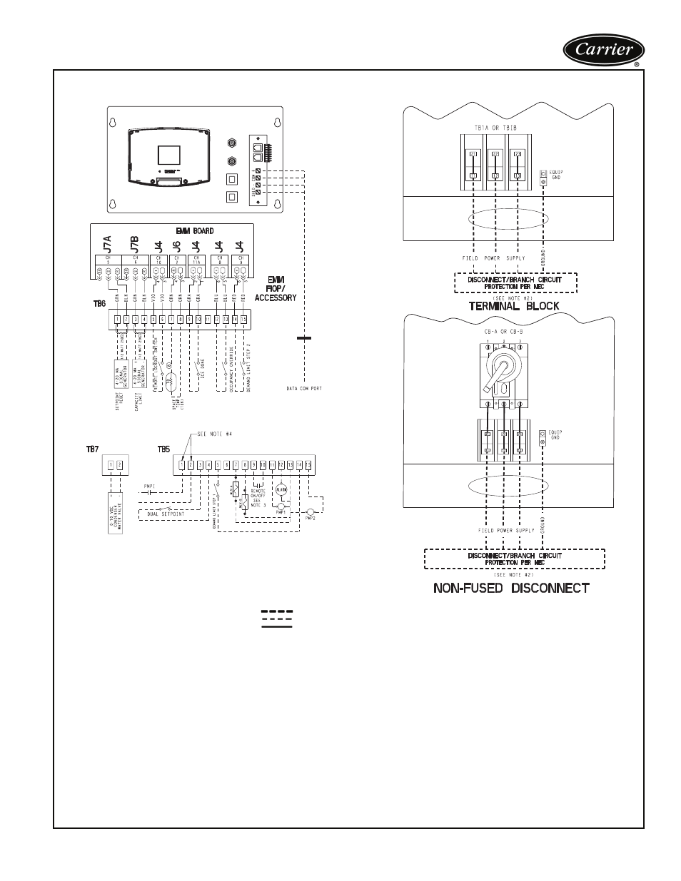
Typical control wiring schematics
30XW UNIT CONTROL WIRING SCHEMATIC
LEGEND
AWG
— American Wire Gage
NEC
— National Electrical Code
CB
— Circuit Breaker
PMP
— Chilled Water Pump
COM
— Communication Port
PMPI
— Chilled Water Pump Interlock
EMM
— Energy Management Module
TB
— Terminal Block
EQUIP GND
— Equipment Ground
Field Power Wiring
FIOP
— Factory-Installed Option
Field Control Wiring
MLV
— Minimum Load Valve
Factory-Installed Wiring
NOTES:
1. Factory wiring is in accordance with UL 1995 standards. Field modifica-
tions or additions must be in compliance with all applicable codes.
2. Wiring for main field supply must be rated 75C minimum. Use copper for
all units. Incoming wire size range for the terminal block is #4 AWG to
500 kcmil for single point power (two conductors per phase). Incoming
wire size range for the terminal blocks for dual point power option is
#4 AWG to 500 kcmil for single point power (one conductor per phase).
Incoming wire size range for 200/300-v models is 3/0 to 500 kcmil for sin-
gle point power (one conductor per phase).
3. Terminals 9 and 10 of TB5 are for field external connections for remote
on-off. The contacts must be rated for dry circuit application capable of
handling a 24-vac load up to 50 mA.
4. Terminals 1 and 2 of TB5 are for external connections of chilled water
pump interlock. The contacts must be rated for dry circuit application
capable of handling a 24-vac load up to 50 mA.
5. Terminals 11 and 13 of TB5 are for control of chilled water pump 1
(PMP 1) starter. Terminals 15 and 13 of TB5 are for control of chilled
water pump 2 (PMP 2) starter. Remove factory-installed jumper when
using pump interlock. The maximum load allowed for the chilled water
pump relay is 5-va sealed, 10-va inrush at 24-v. Field power supply is not
required.
6. For control of chilled water pumps, a set of normally open contacts rated
for dry circuit application must be supplied from field-supplied pump
starter relay. Connect contacts directly to connector at main base board
channel 18.
7. Terminals 12 and 13 of TB5 are for an alarm relay. The maximum load
allowed for the alarm relay is 10-va sealed, 25-va inrush at 24-v. Field
power supply is not required.
8. Make appropriate connections to TB6 as shown for energy management
board options. The contacts for occupancy override, demand limit, and
ice done options must be rated for dry circuit application capable for han-
dling a 24-vac load up to 50 mA.
9. Terminal blocks TB5 and TB6 are located in the display panel box for all
units. Refer to certified dimensional drawing for each unit to get the exact
locations.
10. Refer to certified dimensional drawings for exact locations of the main
power and control power entrance locations.
11. For control of condenser pump, connect field-supplied relay (max 5-va
sealed, 10-va inrush at 24-v) directly to connector at main base board
channel 22.
12. For head pressure control option, 0-10-vdc signal wires are factory-
installed (violet and brown) from HGBP/COND board channel 9. Refer to
controls manual for application with field-supplied water regulating valve.
a30-4697