Fusing - 21tr plus, Wiring - 21tr plus, Flash pattern selection - 21tr plus – Code 3 21TR & 21TR Plus User Manual
Page 10: Warning
10
Fusing - 21TR Plus
TM
The light bar should be installed with an external fuse or circuit breaker in the RED lead of the 2 conductor 10 AWG power cable of the
21TR Plus™ bar. The recommended external fuse size for the light bar is 30A. The internal circuitry of the Central Controller is reverse
polarity protected. Each output on the Central Controller board is protected against over current and over heating with automatically
resetting output devices.
wiring - 21TR Plus
TM
Connect the black lead to a solid frame ground (earth), preferably the (-) or ground (earth) side of the battery, and the power wire to
the +12V terminal of the battery. Connect the remaining wires in the 16 conductor cable as shown in Table 3.
For the ArrowStik® function, connect the appropriate control wires to any control switch capable of providing +power at approximately
25ma current. As noted in the wire description, connecting both the LEFT Arrow and RIGHT Arrow wire to +power at the same time
enables the Center-Out ArrowStik function.
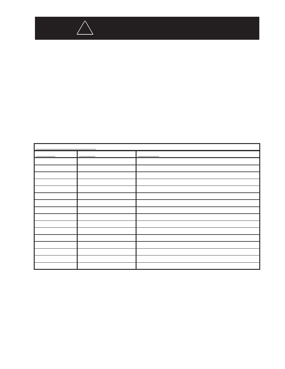
Table 3 - Control Wire Definitions - 21TR Plus
TM
Note: All control inputs are +power enabled.
Control Input Function Definition
wire Color
Function
description
GRN/BLK
Level 1
Level 1 Emergency Mode
WHT/BLK
Level 2
Level 2 Emergency Mode
RED/BLK
Level 3
Level 3 Emergency Mode
ORG/BLK
Take Down lights
Take Down Lights Steady Burn (overrides Take Down Flash)
BLU/BLK
Rear Cut-Off
Blacks-Out Rear Facing LEDs
GRN/WHT
Front Cut-Off
Blacks-Out Front Facing LEDs
RED/WHT
Right Alley Light
Right Alley Steady Burn (overrides Alley Light Flash)
BLK/WHT
Left Alley Light
Left Alley Steady Burn (overrides Alley Light Flash)
WHT
ArrowStik Flash
ArrowStik Flash (overrides L1, L2 & L3 for rear of light bar)
BLK/RED**
Pattern Select
Pattern Select for ArrowStik, L1, L2 & L3, enables test mode)
BLK
Take Down Flash
Enables Take Down Lights Wig/Wag Flash
RED*
ArrowStik Left
Left ArrowStik (overrides L1, L2 & L3 for rear of light bar)
GRN
Cruise Lights
End LEDs only (overridden by all other functions except for Dim)
ORG*
ArrowStik Right
Right ArrowStik (overrides L1, L2 & L3 for rear of light bar)
BLU
Light bar DIM
Sets LED to Dim mode
BLU/WHT
Alley Light Flash
Enables Alley Light Wig/Wag Flash
Flash Pattern Selection - 21TR Plus
TM
The Pattern Select wire is the BLK/RED wire in the 16 conductor control cable and is activated by momentarily touching the wire to
+12V. Reference Table 4 for flash patterns.
Step 1
Power-up the light bar by connecting the Red wire to +12V and the Black wire to ground, and select Level 1 on a user-purchased 3
Level controller or, if the Lightbar is not yet connected to a controller, energize Level-1 by connecting the GRN/BLK wire in the 16
conductor control cable to +12V.
Step 2
Observe the flashing pattern operation and determine which pattern is in operation for Level-1. Refer to Table 1. This table shows the
available flash patterns. Note: the Factory Default is different and identified in the table for each of the flash mode Levels (L1, L2, L3).
Once the flash pattern has been determined, proceed to Step 3.
This Product contains high intensity LED devices. To prevent eye damage, DO NOT
stare into light beam at close range.
wARNING!
!