Aw4rn1ii0 – Craftsman 358.798260-32cc User Manual
Page 7
Attention! The text in this document has been recognized automatically. To view the original document, you can use the "Original mode".
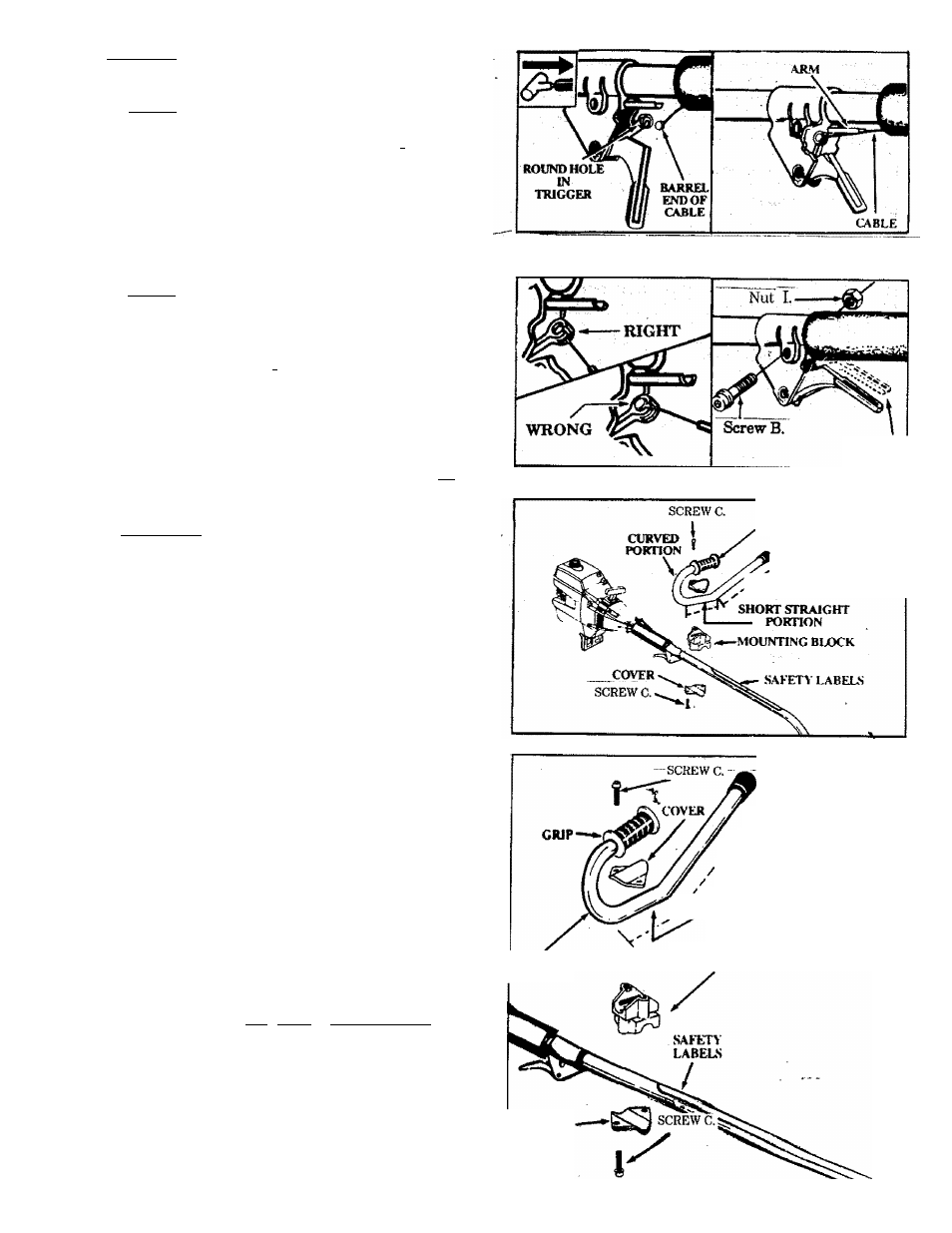
2.THmcrrrLE CABLE
fCAimowil Do not kink the throttle cable.___________ _
a. Slide the Throttle Trigger Housing away from the
Foam Grip.
NOTE: Before performing step “b”, push the barrel
end of thè throttle cable into the sheath until the
barrel contacts the sheath.____________ f
b. Insert the Throttle Cable through the tunnel in the
Foam Grip until the end of the Cable extends at
least 2 inches be^nd the Grip.
c. Hold the Trigger away from the Drive Shaft Hous
ing and insert the barrel end of the Throttle Cable
into the round opening in the Trigger. __________
NOTE: When inserting the barrel end of the
Throttle Cable into the round opening in the
Trigger, make sure that the barrel is completely
inserted and the Throttle Cable is located in the split
in the Arm. __ _____ , ’
d. Push the Trigger back into the Housing while guid
ing the Cable through the split in the aim. Guide^
the arm into the Foam Grip tunnel while replacing,
the Throttle Trigger Housing flush against the Grip?
e. Hold Trigger against the Foam Grip while insert- '
ing the screw “B.” and Nut “I.” See Caution below.
1/8 "PLAY
ICAUTIOM; I Do not overtighten the screw. Make
sure the trigger will move freely. There must be at
least 1/8 "free play in the trigger. Make sure the
trigger will move freely so the engine can fully__________
return to idle when the trigger is released. The
trimmer head must not turn at Idle speed to avoid
serious injury to the operator and others.
3.HANDLEBAR
GRIP
\
BARRIER
PORTION
i^WARNlNG
The handlebar mounting block must be placed above the
point of the arrow on the safety labels. The handlebar
is a barrier to keep the blade away from the operator’s
feet.
a. Position either side of the mounting block on the^
drive shaft Hou'sing above the arrow on the Safety
Labels.________________
b. Place one of the covers below the drive shaft Hous
ing and secure it to the mounting block with 2
screws finger^ti^ten only.
c. Align the Handlebar with the straight barrier por
tion to the left and the curved portion to the right.
d. Position the Mounting Block between the arrows
on the short, straight section of the.Handlebar.
e. Place the remaining Cover over the Handlebar and
secure it with two
screws
“C.”;
finger tighten onlyT
f. Be sure the Handlebar is installed correctly, then
- tighten each screw securely with a wrench.
AW4RN1II0
The long, straight portion of the Handlebar must be
installed to provide a barrier between the operator
and the spinning blade.
>
/
BARRIER
portion
CURVED
PORTION
Cs«' SHORT
X ^STRAIGHT
PORTION
MOUNTINt:
BLOCK
COVER