To remove snow thrower from carton (see fig 1), How to set up your snow thrower, To set the skid height – Craftsman 536.885020 User Manual
Page 7: Assembly
Attention! The text in this document has been recognized automatically. To view the original document, you can use the "Original mode".
ASSEMBLY
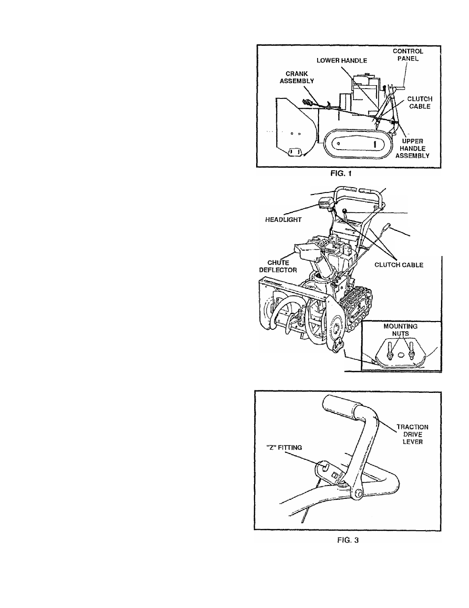
Figure 1 shows the snow thrower in the shipping position
Figure 2 shows the snow thrower completely assembled.
Reference to the right and left hand side of the snow
thrower is from the operator's position at the handle.
TO REMOVE SNOW THROWER
FROM CARTON (See Fig 1)
®..... Cut all four corners of the carton from top to bottom
and lay the panels flat.
•
Cut the cable ties attached to the augers .
•
Cut and discard the ties that secure the crank
assembly and place the assembly aside
®
Remove the packing mate rial f rom t he co ntrol pan e I.
•
Cut and discard the packing securing the clutch
cables to the lower handle,
® With two 9/16 inch wrenches, loosen (do not re
move) both bolts securing the upper and lower
handies Swing the upper handle into the operating
position.
NOTE: If the cables have become disconnected from the
clutch levers, reinstall the cables as shown in Figure 3.
® Tighten both bolts securely.
® Roll the snow thrower off the skid by pulling on the
handle.
NOTE; This snow thrower is equipped with a track drive
and can be hard to push when the engine is not running
it is easier to pull the snow thrower backward if it must be
moved without the engine running
The drive system may be tight when you first use your
snow thrower.
It
loosens up as you use
it.
HOW TO SET UP YOUR SNOW
THROWER
TO SET THE SKID HEIGHT
For shipping, the height adjust skids are reversed To use
your snow thrower, you need to remove the height adjust
skids and reinstall as shown in Fig. 2 Then adjust the
height adjust skids for surface condilions as follows:
® Loosen the mounting nuts on the skids (See Fig 2)
® Place the extra shear bolts (in the parts bag) under
each end of the scraper bar near but not under the
skids.
® Push each skid up or down until it touches the
ground and the scraper bar is resting on each shear
bolt. Be sure the skids are set at the same height on
both sides
® Tighten the mounting nuts
AUGER DRIVE
LEVER
TRACTION DRIVE
LEVER
SHIFTER
LEVER
CRANK
ASSEMBLY
HEIGHT ADJUST
SKID
FIG. 2