Bude drive belt replacement, To remove belt, To install belt – Craftsman 987.889000 User Manual
Page 27: Blade brake replacement, To remove blade brake, To install brake, Service and adjustments, Figure 5-7: blade drive control
Attention! The text in this document has been recognized automatically. To view the original document, you can use the "Original mode".
SERVICE AND ADJUSTMENTS
BUDE DRIVE BELT
REPLACEMENT
Follow this procedure to remove
and replace the blade drive belt.
An assistant will be needed.
To Remove Belt
1. stop engine, wait for aii parts
to stop moving, and disconnect
spark piug wire.
2. Disengage blade drive control
(Figure 5-7) by releasing all con
trols on the mower.
3. Remove belt cover (see “Belt
Cover Removal”).
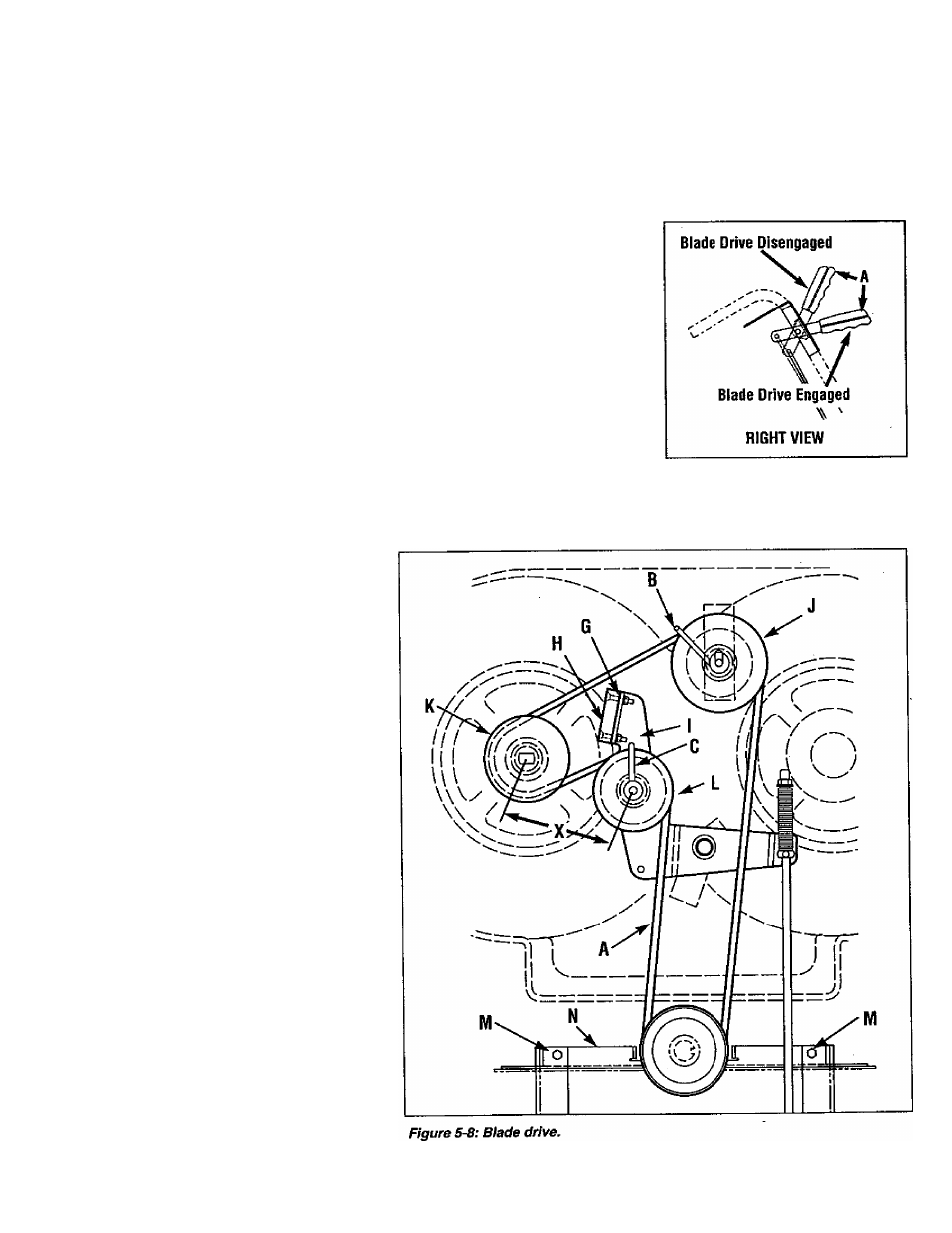
4. Loosen belt guides (B and C,
Figure 5-8).
5. Move flap bracket (N, Figure
5-8) out of the way by loosening
two screws (M).
6. Remove belt (A, Figure 5-8)
from around sheaves.
To Install Belt
1. Route belt (A, Figure 5-8)
around sheaves as shown.
2. Have an assistant hold down
Operator Presence Control and
then push the Blade Drive Control
fonward until it latches in place
(Figure 5-7).
3. With the Blade Drive Control
lever engaged, adjust and tighten
belt guide (B) to 1/32 -1/16“ away
from tensioned belt. (Be sure that
belt does not contact belt guide
when belt is under tension.) Se
cure belt guide (C) rotated into po
sition as shown in Figure 5-8.
4. Disengage Blade Drive Control.
5. Re-tighten two screws (M, Fig
ure 5-8) that secure flap bracket
(N).
6. Reinstall belt cover securely.
Figure 5-7: Blade Drive Control.
BLADE BRAKE REPLACEMENT
Follow this procedure to install a
new blade brake.
To Remove Blade Brake
1.
Stop engine, wait for ail parts
to stop moving, and disconnect
spark piug wire.
2.
Remove belt cover as described
in “Belt Cover Removal” instruc
tions.
3. Remove hardware (G, Figure
5-8) securing blade brake (H).
4. Remove old brake (H) from idler
arm (I).
To Install Brake
1. Position new brake (H) in place
on idler arm (I).
2. Center brake in sheave groove
and secure brake (H) with hard
ware (G) removed earlier.
3. Reinstall belt cover securely.
4. Test operation of blade brake
(see “Blade Brake Control Test" on
Page 22).
27