Wheel drive control, Caution, Cutting height control lever – Craftsman 987.889000 User Manual
Page 15: Mulcher cover, Danger, Operation, Figure 3-5, Figure 3-7
Attention! The text in this document has been recognized automatically. To view the original document, you can use the "Original mode".
OPERATION
Wheel Drive Control
Use this lever {D, Figure 3-5) to
engage and disengage drive to the
wheels.
To engage the wheels, first select
a fonward or reverse gear with the
Gear Select Lever and press the
Operator Presence Control (A, Fig
ure 3-5) against the handlebar
grip. Then, squeeze the Wheel
Drive Control lever (D) up against
the handlebar grip. The ground
speed can be varied in any gear by
increasing (to go faster) or de
creasing (to go slower) pressure
on the lever. To avoid sudden ac
celeration, slowly squeeze the
lever when first engaging the
wheels.
Release the Wheel Drive Control
to disengage the wheels. The
wheels will gradually slow to a
stop. NOTE; To stop the wheels
quickly, release the Operator Pres
ence Control along with the Wheel
Drive Control.
When starting the engine, the
Wheel Drive Control should be dis
engaged (released). This helps to
ensure that the wheels will not start
turning when the engine starts.
CAUTION
Do not engage the Wheel
Drive Control without first en
gaging the Operator Presence
Control. Doing so could re
sult in wear or damage to the
wheel brake mechanism.
A ~ OPERATOR
PRESENCE CONTROL
Disengage
Engage
Engage
)isengage
/”
D-WHEEL
DRIVE CONTROL
Figure 3-5
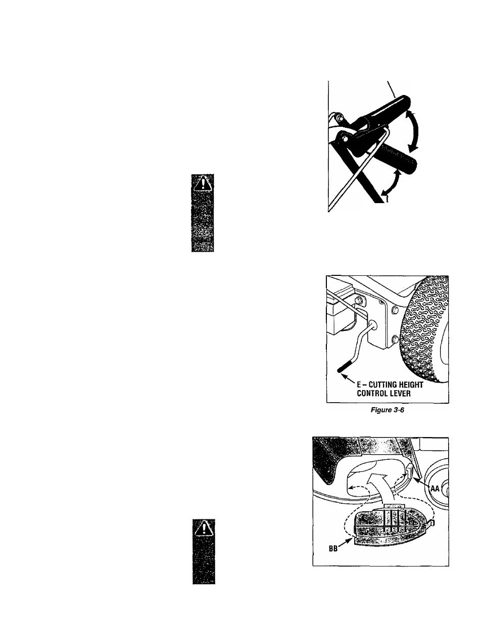
Cutting Height Control Lever
This lever (E, Figure 3-6) is used
to adjust the mower cutting height.
The cutting height can be adjusted
from 1 to 4 inches.
Turn the lever clockwise to raise
the cutting height or counterclock
wise to lower the cutting height. A
decal and pointer (not illustrated)
on the right side of the mower deck
show the cutting height settings
ranging from A (highest) to G (low
est). Note that the actual cutting
heights will vary according to soil
conditions.
Mulcher Cover
To use the mulching feature, in
sert the mulcher cover (Figure 3-7)
securely in the right side of the
deck beneath the discharge chute.
Insert the front tab of the cover
into the mower front support brack
et (AA, Figure 3-7). Then push the
cover into place by sliding the
cover rearward, making sure that
the slot (BB) in the cover is com
pletely engaged in the rear edge of
the deck opening.
Remove the mulcher cover if you
want to do side-discharge mowing.
The mulcher cover is
pre-installed at the factory.
NOTE: The mulcher cover is
designed to keep the discharge
chute raised up while you mow.
When the cover is removed, the
discharge chute lowers.
DANGER
Before installing or re
moving mulching cover,
stop engine, wait for parts
to stop moving, and dis
connect spark plug wire.
Figure 3-7
15